Do you have a question about the Abloy EL460 and is the answer not in the manual?
Details on compliance with EN 179 and EN 1125 standards.
Mapping of wiring terminals to functions and states.
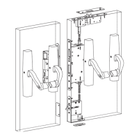
Operation of the handle on the panic side.
Operation of the handle on the electrically controlled side.
Setting the lock for fail-locked electrical function.
Setting the lock for fail-unlocked electrical function.
Important note regarding unscrewing the Allen screw.
Instructions for attaching the cable to the lock.
Procedure for installing spindle adapters.
Setting the lock for fail-unlocked electrical function.
Setting the lock for fail-locked electrical function.
Operation of the handle on the panic side.
Operation of the handle on the electrically controlled side.
| Operating Temperature | -20°C to +60°C |
|---|---|
| Bolt Throw | 20 mm |
| Locking Principle | Motorized bolt |
| Compatibility | Access control systems |
| Application | Doors |
| Operating Voltage | 12 V DC |
| Monitored Functions | Bolt position, door position |
| Suitable for | Fire doors |