EasyManua.ls Logo

Abloy CERTA MP420 User Manual

Abloy CERTA MP420
36 pages
To Next Page IconTo Next Page
Page #1 background imageLoading...
Page #1 background image
Public (Performance)
EL420, EL422, EL520, EL522, EL524
MP420, MP422, MP520, MP522, MP524
MP420 FLAT, MP520 FLAT. MP524 FLAT
PE420, PE422, PE520, PE522
Question and Answer IconNeed help?

Do you have a question about the Abloy CERTA MP420 and is the answer not in the manual?

Abloy CERTA MP420 Specifications

General IconGeneral
Security GradeEN 12209 Grade 6
Key OverrideYes
Cylinder typeAbloy PROTEC2 cylinder
KeyingKeyed alike (KA), Master keyed (MK)
Lock TypeMortise
Key SystemAbloy PROTEC2

Summary

Technical Specifications

Power and Electrical Parameters

Details on voltage, current ratings, and relay specifications for lock operation.

Adjustable Delay Settings

Information on configuring the lock's delay functions for operation.

Function Settings and Monitoring

Settable Mechanical Functions

Description of adjustable mechanical features like trigger bolt direction.

Monitoring Output Signals

Explanation of the status signals provided by the lock for monitoring.

Product Compliance and Standards

Emergency Exit Device Compliance (EN 179)

Details product compliance with EN 179 standard for emergency exits.

Panic Exit Device Compliance (EN 1125)

Details product compliance with EN 1125 standard for panic exits.

Electromagnetic Compatibility and Fire Resistance

Compliance with EMC and fire resistance standards.

Installation Guidelines and Hardware Compatibility

EN 179 Installation Details

Specific installation requirements and diagrams for EN 179.

EN 1125 Installation Details

Specific installation requirements and diagrams for EN 1125.

Compatible Hardware Manufacturers

Lists manufacturers of compatible hardware for lock installation.

EN 1125 Installation Diagrams and Effeff Compatibility

EN 1125 Installation Specifications

Diagrams and specifications for EN 1125 installations.

Effeff and Abloy DO 6.7 Product Data

Table detailing compatibility with Effeff and Abloy DO 6.7.

Hardware Compatibility and Safety Precautions

EN 179 Hardware Compatibility Details

Specific compatibility details for EN 179 hardware.

EN 1125 Hardware Compatibility Details

Specific compatibility details for EN 1125 hardware.

Product Safety and Modification Warnings

Important safety notices and restrictions on product modifications.

Wiring Diagram and Control Signals (EA420)

Power and Terminal Connections

Specifies power inputs and terminal functions for wiring.

Dip Switch Settings and Functions

Guide to configuring dip switches for lock operation.

Monitoring and Sabotage Loop Configuration

Details on setting up monitoring and sabotage detection loops.

Installation Best Practices and Tolerances

Door and Frame Alignment

Instructions for ensuring doors and frames are properly aligned.

Surface Mounted Lock Case Gaps

Specifies acceptable tolerances for surface-mounted locks.

Cable Routing and Drilling Specifications

Guidance on routing cables and required drilling sizes.

Narrow Profile Door Installation Guidelines

Narrow Door Frame Alignment

Alignment requirements for narrow profile doors.

Narrow Profile Door Gap Tolerances

Acceptable gap tolerances for narrow profile installations.

Narrow Profile Cable Routing

Cable routing instructions for narrow profile doors.

Drilling Scheme for EL Series Locks

Drilling Procedure and Specifications

Step-by-step drilling instructions and dimensions for EL series.

Drilling Guidance by Fitting Type

Advice on selecting drill bits based on hardware type.

Drilling Scheme for EL520/522 & PE520/522 Series Locks

Forend Drilling Dimensions

Specific dimensions for drilling the forend of EL520/522/PE520/522.

Drilling Guidance by Fitting Type

Advice on selecting drill bits based on hardware type.

Drilling Scheme for EL524 Lock

EL524 Forend Drilling Details

Detailed drilling dimensions for the EL524 forend.

Drilling Guidance for Installations

General advice on drilling for installations.

Drilling Schemes for EA Series Components

EA321 Drilling Specifications

Specific drilling dimensions for EA321.

EA323 Drilling Specifications

Specific drilling dimensions for EA323.

EA322/324-329/332 Drilling Specifications

Drilling dimensions for multiple EA series components.

MP420/MP422 Mechanical Assembly Details

MP420/MP422 Housing and Component Diagrams

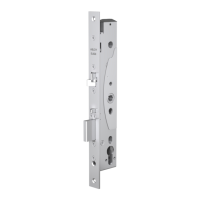
Diagrams showing housing and internal components for MP420/MP422.

Associated Hardware (EA306, EA322-332) Diagrams

Diagrams of related hardware components for MP420/MP422.

MP420 FLAT Mechanical Assembly Details

MP420 FLAT Housing and Component Diagrams

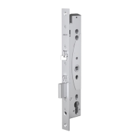
Diagrams of MP420 FLAT housing and components.

Associated Hardware (EA322-329) Diagrams

Diagrams of related hardware for MP420 FLAT.

MP520/MP522 Mechanical Assembly Details

MP520/MP522 Housing and Component Diagrams

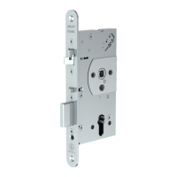
Diagrams of MP520/MP522 housing and components.

MP524 Mechanical Assembly Details

MP524 Housing and Component Diagrams

Diagrams of MP524 housing and components.

MP520 FLAT Mechanical Assembly Details

MP520 FLAT Housing and Component Diagrams

Diagrams of MP520 FLAT housing and components.

MP524 FLAT Mechanical Assembly Details

MP524 FLAT Housing and Component Diagrams

Diagrams of MP524 FLAT housing and components.

MP520/522/524 Series Assembly Details with Hardware

MP520/522/524 Assembly Diagrams

Diagrams showing the assembly of MP series locks.

Associated Hardware (EA321, EA323) Diagrams

Diagrams of related hardware for MP series.

MP520/522/524 Series Handle Assembly Details

MP520/522/524 Handle Assembly Diagrams

Diagrams showing handle assembly for MP series.

Associated Hardware (EA306, LP780) Diagrams

Diagrams of related hardware for MP series handles.

EL420/422 & PE420/422 Assembly Steps

Forend and Housing Assembly (A)

Steps for assembling the forend and housing.

Trigger Bolt and Handle Assembly (B)

Steps for assembling the trigger bolt and handle.

Allen Screw Installation Caution (C)

Important caution regarding Allen screw installation.

EL520/522/524 Series Assembly Steps

Lock Case Component Assembly (D, E)

Steps for assembling lock case components.

Wiring and Control Assembly (F, G)

Steps for assembling wiring and control elements.

Handle Installation (H)

Steps for installing the handle.

Door Configuration: Outside vs. Inside Views

EL/MP Series Door Configuration (OUT/IN)

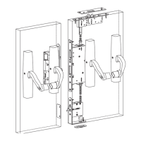
Diagrams showing door configuration from outside and inside.

EL520/522/524/MP Series Door Configuration (OUT/IN)

Door configuration views for EL520/522/524/MP series.

Handle Installation: Outside vs. Inside Views

EL/MP Series Handle Installation (OUT/IN)

Handle installation views for EL/MP series.

EL520/522/MP Series Handle Installation (OUT/IN)

Handle installation views for EL520/522/MP series.

Product Recycling and Manufacturer Information

Recycling Instructions for Electronic Components

Guidelines for recycling electronic parts.

Manufacturer Contact and Warranty Information

Details about the manufacturer and warranty.

Related product manuals