Do you have a question about the Abloy EL580 and is the answer not in the manual?
Selectable mechanical functions including handing, bolt throw, and controlled side.
Solenoid control for enabling or disabling the handle operation.
Information signals for deadlock status and handle engagement.
Requirement for 14 mm bolt throw on fire doors.
Details on standards such as EN 179, EN 1125, and EMC.
Maximum voltage and current values for internal micro switches.
Essential safety features for EN 179/EN 1125 compliance.
Prohibition of unauthorized modifications to the product.
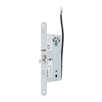
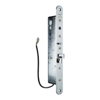
Diagrams showing electrical connections for different regions.
Warning against using handle position for control signals.
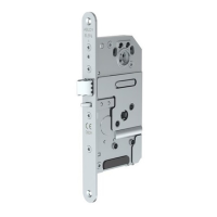
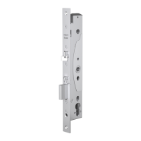
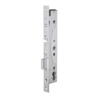
Detailed drilling schemes for various lock models.
Specifications for backset (L) dimensions for EL580 and PE580.
Recommended space for routing wires within the lock case.
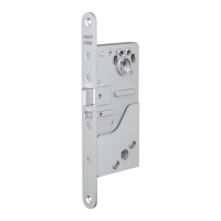
Step-by-step illustration for assembling lock components.
Detailed steps for mounting and connecting internal parts.
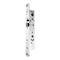
Illustrations showing adjustments for mechanism parts.
Specific steps for setting bolt throw for fire doors.
Explanation of handle operation modes (mechanical/electrical).
Illustrations of handle installation and operation.
Illustrations of oval handle variants for EL580 and EL582.
Illustrations of standard handle variants for EL580 and EL582.
Illustrations of handle variants for the PE580 model.
Information on materials requiring separate recycling, like electronics.
Guidance on disassembling and sorting materials for recycling.
| Operating Voltage | 12-24 V DC |
|---|---|
| Operating Temperature | -20°C to +60°C |
| Weight | 1.2 kg |
| Finish | Stainless steel |
| Bolt Throw | 20 mm |
| Protection Class | IP54 |
| Locking Direction | Reversible |
| Current Consumption | Max 500 mA |
| Monitored Functions | Bolt position |
| Suitable for | Interior doors |
| Backset | 50 mm |