Do you have a question about the Abrams StarEye Series and is the answer not in the manual?
Essential safety guidelines for installation and use to prevent damage or injury.
Details on available flash patterns and their synchronized phase operations.
Explains wire connections, dual switch plug functions, and pattern selection.
Covers recommended operating conditions, physical dimensions, and common troubleshooting steps.
Outlines the 5-year warranty terms, coverage, and limitations.
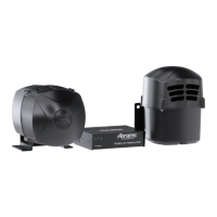
Visual representation of the magnetic mount components with part identification.
Detailed list of parts included in the permanent mount assembly.
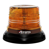
The Abrams StarEye Series Model B-S1200 is an LED beacon designed for warning and signaling purposes, featuring a robust construction and a variety of flash patterns to suit different operational needs. This device is intended for professional use and requires proper installation and handling to ensure safety and optimal performance.
The primary function of the StarEye Series beacon is to provide high-intensity visual signaling through its LED array. It offers a comprehensive set of 30 flash patterns, including single, double, triple, and quad flashes, as well as rotator simulations. These patterns are categorized by their flashes per minute (FPM) and phase, allowing for synchronized operation with multiple units. For instance, patterns like "Single Flash 75 FPM Phase 1 (SIM) - sync" and "Double Flash 75 FPM Phase 2 (SIM) - sync" indicate synchronized capabilities, where units can flash in unison or alternate phases. Specific patterns like "ECE R65 Rotator Flash 60" and "CA T13 Double Flash 75FPM (SIM)" comply with regional regulatory standards, highlighting its versatility for various jurisdictions. The "ModuFlash sim." pattern suggests a unique or modulated flash, while "Autorun (Random)" provides dynamic, unpredictable signaling. A "Steady Burn" option allows for continuous illumination, and "OFF" turns the unit off.
The beacon's operation is controlled via a dual-switch plug assembly, which includes a power on/off switch and a pattern switch. This allows users to easily cycle through the available flash patterns. The pattern switch offers intuitive control: a press of less than 1 second advances to the next pattern, a press between 1 and 3 seconds reverts to the previous pattern, and a press between 3 and 5 seconds resets the device to its factory default pattern. Holding the switch for more than 5 seconds will turn the unit off. This sequential control mechanism ensures that users can quickly select the desired pattern without complex programming.
A key feature of the StarEye Series is its synchronization capability. Up to eight beacons can be synchronized, meaning they can flash together or in alternating phases, enhancing visibility and impact. This is particularly useful for larger vehicles or multiple units operating in convoy, where coordinated signaling is crucial. The synchronization function is activated by applying the yellow wire to the black wire, enabling a cohesive visual warning system.
The StarEye Series beacon is designed for external mounting, with options for both permanent and magnetic installations. The magnetic mount version, indicated by the "MAG MOUNT" designation, provides flexibility for temporary or easily removable applications. The device is constructed with durable materials, including a PC cover, ABS base, and an aluminum heat sink, ensuring longevity and resistance to environmental factors. The inclusion of an O-ring and gasket further enhances its weather resistance, making it suitable for outdoor use in various conditions.
The recommended operating environment for the beacon is an ambient temperature range of -30 to 50°C and a relative humidity of 10 to 85%, non-condensing. This broad range indicates its suitability for diverse climates. The device operates on a positive +10~30VDC power supply, requiring a 3A fuse for protection. Proper electrical connection is emphasized, with the recommendation to connect the product's ground wire directly to the NEGATIVE (-) battery post for optimum efficiency.
Safety is a paramount consideration in the design and usage of the StarEye Series. The manual explicitly warns against staring directly into the high-intensity LEDs to prevent momentary blindness or eye damage. It also provides critical instructions regarding installation, such as avoiding air bag deployment areas and ensuring no vital vehicle components are damaged during drilling. The user/installer assumes full responsibility for determining the proper mounting location to ensure ultimate safety for all passengers. The dual-switch plug assembly, with its clear power and pattern controls, is designed for safe operation, but users are cautioned against attempting to activate or control the device in hazardous driving situations.
Maintenance for the StarEye Series beacon is straightforward, focusing on regular inspection and proper cleaning. Users are advised to inspect and operate the product regularly to confirm its proper operation and mounting condition. This proactive approach helps identify and address any potential issues before they escalate.
For cleaning the outer lens, only soap and water should be used. The manual specifically warns against using a pressure washer, as this could damage the device. This simple cleaning instruction helps preserve the clarity of the lens and the effectiveness of the light output.
Troubleshooting guidance is provided to address common issues. If the LED beacon fails to function, users are instructed to check the power supply connection to ensure it is correct and free of short circuits. Verifying that the power switch is in the "ON" position is another basic step. If the "OFF" pattern is inadvertently selected, the blue wire touching the black wire for over 5 seconds will switch it to the OFF pattern, and touching it for over 1 second will turn it back on. Finally, checking if the plug fuse is broken is a crucial step, as a blown fuse can prevent the device from receiving power.
The device is designed for durability, with components like the aluminum heat sink and robust housing contributing to its long-term reliability. The inclusion of grommets and an O-ring ensures a sealed enclosure, protecting internal electronics from moisture and dust, thereby reducing the need for frequent internal maintenance. The manual also recommends storing the instructions in a safe place for future reference during maintenance or reinstallation, emphasizing a user-friendly approach to long-term care.
| Category | Security System |
|---|---|
| Weather Resistance | IP66 |
| Two-Way Audio | Yes |
| Storage | MicroSD card up to 128GB, Cloud |
| Connectivity | Wi-Fi |
| Motion Detection | Yes, with alerts |