Do you have a question about the Abt ABT-40 and is the answer not in the manual?
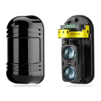
Identifies key components of the transmitter and receiver units, including indicators and adjustment knobs.
Explains the meaning of the receiver's indicator lights: LEVEL, ALARM, and GOOD.
Advises on avoiding impediments, unstable bases, and direct sunlight for optimal performance.
Details horizontal and vertical adjustment ranges for optimal beam alignment.
Provides specifications for guarding distance and beam spread diameter for different models.
Step-by-step guide for mounting the main detection unit and connecting wiring.
Instructions for installing the fixed mounting bracket for the detector.
Table showing allowed wiring distances based on cable gauge for transmitter/receiver.
Aligns the detector using the viewfinder and GOOD indicator status.
Aligns the detector by maximizing voltage output at test holes.
Adjusts the receiver's response time based on intruder speed (high speed to slow walking).
Verifies transmitter and receiver LED indicators during transmitting, guarding, and alarm states.
Lists common faults, their causes, and suggested solutions for transmitter and receiver issues.
Details technical specifications including alert distance, detection mode, power, and dimensions.
Illustrates recommended installation setups and provides examples of mounting brackets.
Shows the physical appearance and dimensions of the detector and its mounting brackets.
| Brand | Abt |
|---|---|
| Model | ABT-40 |
| Category | Security Sensors |
| Language | English |