Do you have a question about the Abus AZAA10000 and is the answer not in the manual?
Included quick start guide for initial product installation.
Included safety instructions for product usage.
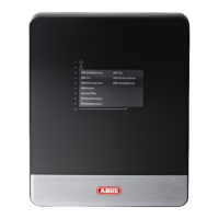
Connections for external communication modules and devices.
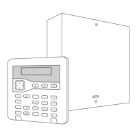
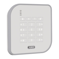
Connection point for the system's user interface keypad.
Terminal for connecting an internal or external loudspeaker.
Outputs for signaling devices like sirens or strobes.
Connection for external siren and strobe warning devices.
Input terminals for alarm detection zones.
Jumper for initiating system restart or bootloader mode.
Connection for resetting system access codes.
Terminating resistor for the RS485 communication bus.
Reserved terminal for diagnostic or engineering purposes.
Connection point for the main power supply transformer.
Connection for the backup battery power supply.
Guidance on choosing a suitable and secure place for the control panel.
Procedure for safely opening the control panel housing.
Instructions for physically attaching the control panel to a surface.
Steps for wiring all system components, excluding the battery.
Procedure for connecting the backup battery to the system.
Instructions for connecting the primary power supply.
Final steps to close unit, power up, and perform initial setup.
| Brand | Abus |
|---|---|
| Model | AZAA10000 |
| Category | Control Panel |
| Language | English |