Hardware and physical integration guideline PCR Sensor A111
Page 17 of 32
2022-03-08 © 2022 by Acconeer – All rights reserved
4.4 Impact on the radiation pattern
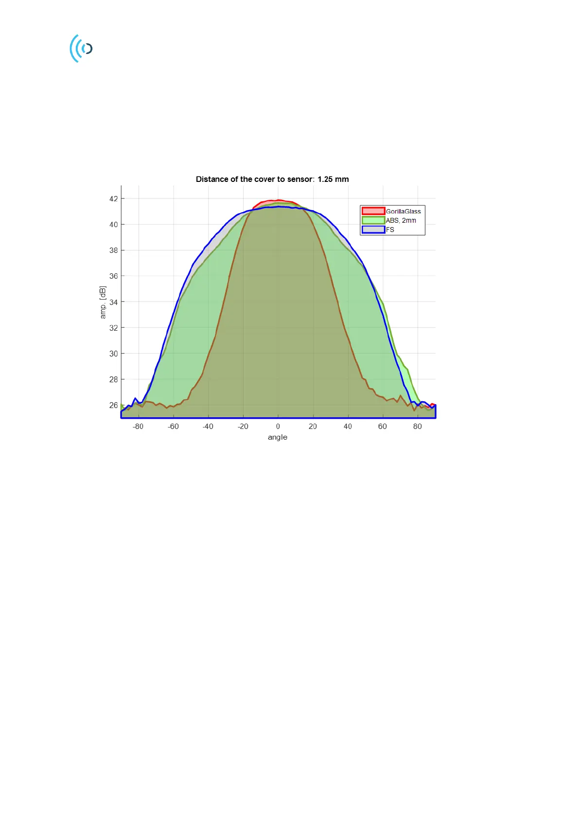
The radar loop radiation pattern of the integrated antennas will be affected by the dome that is put on
top of the sensor. Figure 16 shows the measured radar loop pattern for three different materials, ABS
plastic, gorilla glass and free space.
Figure 16. Impact of the different materials on the radiation pattern, H-plane. Amplitude is stated in one direction
(Tx or Rx side). For Radar Loop Gain (RLG) the values will be doubled.
Figure 17 shows the radar radiation pattern when a radome made of ABS with 2mm thickness is placed
at distances corresponding to the harmonics of the quarter-of-a-wavelength of the radar pulse. The
reference case is FS (Free Space i.e. no cover). Since the radome thickness is not optimal, distances
which correspond to odd harmonics of the quarter-of-a-wavelength have the minimum impact on the
radiation pattern.