Hardware and physical integration guideline PCR Sensor A111
Page 19 of 32
2022-03-08 © 2022 by Acconeer – All rights reserved
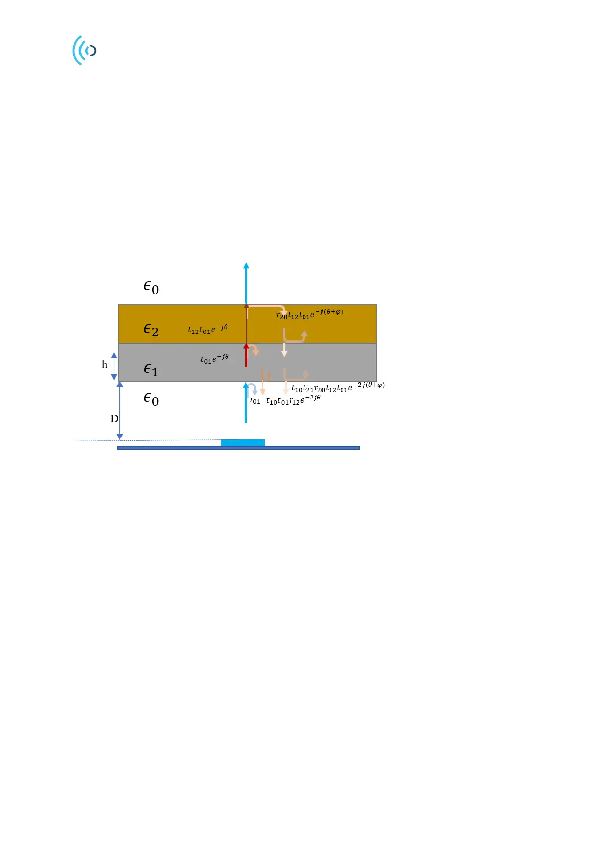
4.5 Multi-layer radome integration
Radomes can also be constructed from a multi-layer dielectric. Particularly, where the thickness of a
single layer dielectric is fixed, thus additional layer can be added to the radome which can act as an
anti-reflection layer. Figure 19 shows the stack-up of a radome made of two dielectric layers and
illustrates the scattering of waves in this scenario. In this scenario, the reflections formed at the
interfaces of the different mediums can be cancelled if the condition below is satisfied:
The layer indicated with
dielectric constant is the main layer and the layer with the
dielectric
constant is the matching layer. Depending on the degree of the freedom, one can find the optimum
thickness or the optimum dielectric constant for the anti-reflection layer.
Figure 19. Illustration of the scattering waves for a two-layer radome.
Another approach is to use an EM simulation tool to find the characteristic of the anti-reflection layer.
For example, Figure 20 shows a sensor integration scenario where the main layer of the radome is made
of a special glass which has a high dielectric constant (~6-7). Therefore, the wave impedance mismatch
between the glass and the air becomes large. To reduce the mismatch, a matching layer with a lower
dielectric is applied between sensor and the screen. To find the optimum dielectric value of the matching
layer, the dielectric constant is varied in the simulation. It can be seen from the results shown in Figure
21 that the gain drops at least 2 dB in case 1, compared to case 2 where the matching layer has a dielectric
constant of 3.