Hardware and physical integration guideline A1 PCR sensors
Page 19 of 30
2024-02-07 © 2024 by Acconeer – All rights reserved
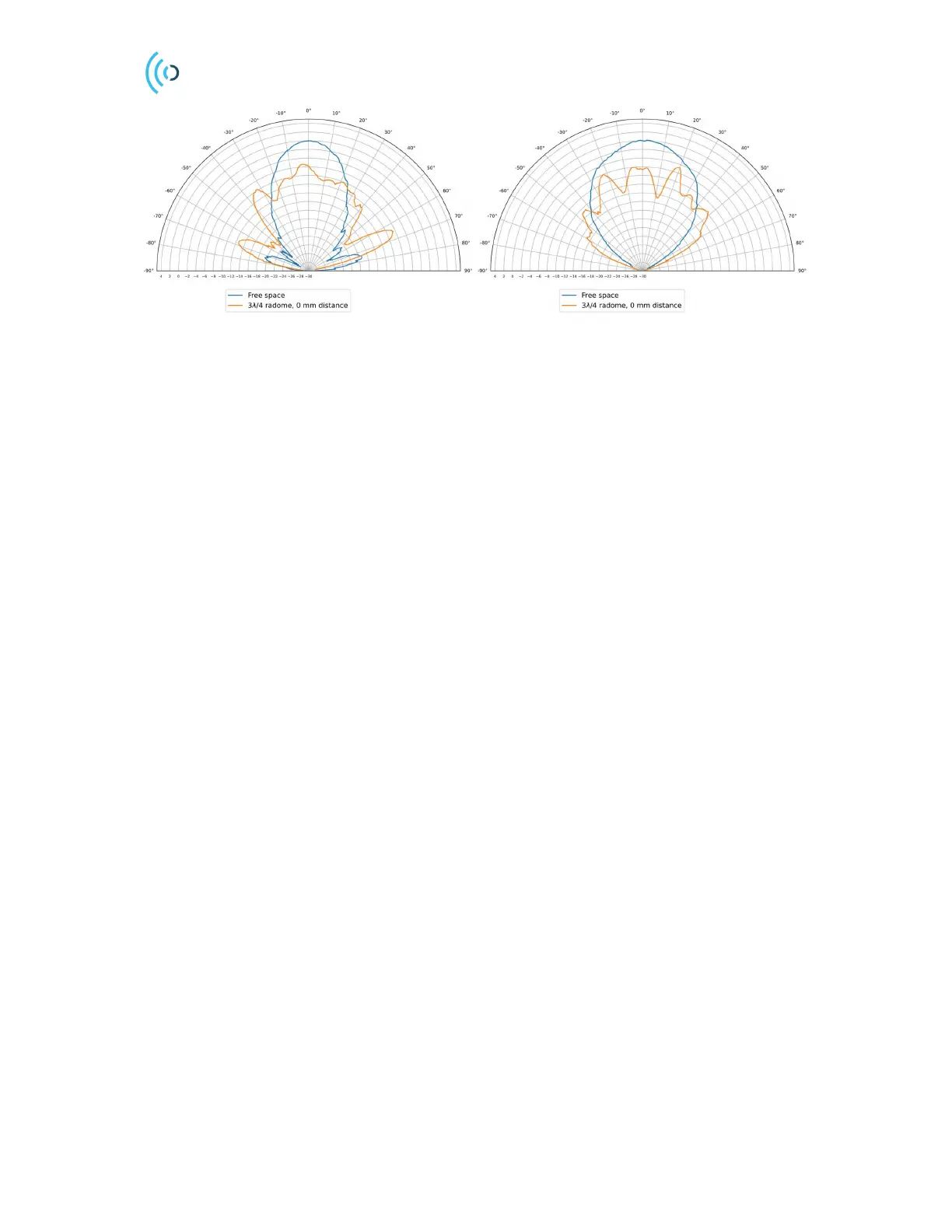
Figure 16: RLG pattern of E-plane and H-plane, cover placed directly on the sensor vs free space. The radial axis is
the amplitude, stated in two directions (Tx and Rx side), i.e. Radar Loop Gain (RLG) and normalized to free space
radiation.