Hardware and physical integration guideline A1 PCR sensors
Page 23 of 30
2024-02-07 © 2024 by Acconeer – All rights reserved
4.2 Lens gain
The lens gain is related to the lens effective area by 𝐺=4𝜋𝐴
/𝜆
, where λ is the wavelength in the
material. Approximating the effective area with the lens inner surface area 𝐴
=𝜋(𝐷/2)
, we obtain
𝐺=𝜋
𝐷
/𝜆
. We thus notice that the lens gain is proportional to the square of the diameter. To get
the lens RLG, we double the lens gain.
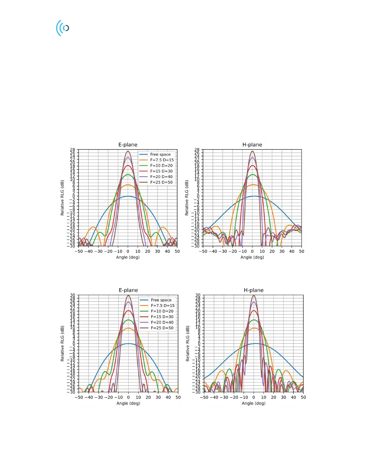
Figure 20 and Figure 21 show simulated RLG pattern plots for the hyperbolic and the plano-convex
lenses for some sample values of F and D. These figures can be used as a rough guideline for choosing
the lens size. Observe that for the same diameter, the plano-convex lens yields somewhat higher gain
compared to the hyperbolic lens. The exact RLG pattern will also depend on the lens housing, choice
of material and PCB size.
Figure 20. Simulated RLG patterns for different size hyperbolic lenses assuming lossless dielectrics.
Figure 21. Simulated RLG patterns for different size plano-convex lenses assuming lossless dielectrics.
 Loading...