Hardware and physical integration guideline A1 PCR sensors
Page 8 of 30
© 2024 by Acconeer – All rights reserved 2024-02-07
3 Electromagnetic Integration
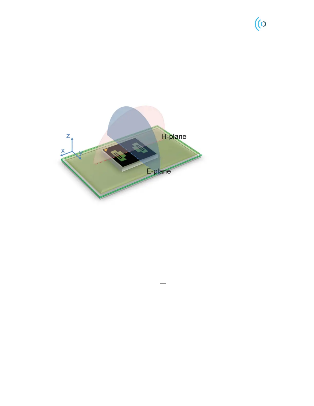
The A111 and A121 pulsed coherent radar sensors are fully integrated 60 GHz radar sensors with
integrated transmitter and receiver antennas. The Tx and Rx antennas are of folded-dipole type and the
E-plane and H-planes are indicated in Figure 3. The RLG patterns can be found in each datasheet, see
[2] and [3].
Figure 3. Sensor mounted on a printed circuit board (PCB). E-plane and H-plane are highlighted with blue and red
color, respectively.
3.1 Radar loop equation
Consider a signal transmitted through free space to a radar target located at distance R from the radar.
Assume there are no obstructions between the radar and the radar target, and the signal propagates along
a straight line between the two. The channel model associated with this transmission is called a line-of-
sight (LOS) channel. For the LOS channel, the corresponding received reflected power from a radar
target, i.e. the signal to noise ratio (SNR), can be defined as
(1)
where R is the distance of the radar to the target, 𝐶 is the radar loop gain, including both the transmitter
and receiver chain (two-ways signal path), 𝜎 is the Radar Cross Section (RCS) of the scattering object
and 𝛾 determines the reflected power of the object’s material. RCS depends on the size and shape of the
scattering object. Moreover, SNR depends on the sensor profile setting. A comprehensive explanation
of the sensor profiles can be found in the Acconeer’s Radar Handbook” [4].
3.2 Radar loop gain pattern
When characterizing the gain, we refer to the radar loop gain defined in the radar equation section.
Figure 4 shows the radar setup configuration for the radar loop radiation pattern measurement. The
 Loading...