Hardware and physical integration guideline A1 PCR sensors
Page 9 of 30
2024-02-07 © 2024 by Acconeer – All rights reserved
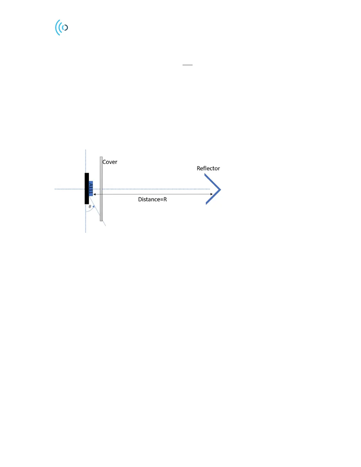
reflector which in this case is a circular trihedral corner is located at the far-field distance from the
sensor. The far-field distance can be determined by the aperture of the sensor and the radar target.
(2)
where A is the largest dimension of either the sensor or the radar target. Far-field is the region where
the radiation pattern shape does not change with the distance. However, the radar works below the far-
field distance with different characteristic than the far-field region with radiation pattern dependency on
the distance.
The service “Sparse IQ” (A121) or the “Envelope detector” (A111) can be used to collect the reflected
signal at the fixed distance from the radar target for different rotation angles. The figure of merit for
amplitude variation stated in the document is the radar loop gain (RLG). RLG includes both transmitter
and receiver gain of the radar.
3.3 PCB layout
This chapter describes means of optimizing the sensor performance by properly designing the printed
circuit board (PCB).
3.3.1 Sensor ground plane size
To maximize the radar loop gain and minimize impact on radiation pattern, it is recommended that the
top PCB layer is a filled copper layer with minimum amount of routing close to the sensor. Figure 5
shows the relative loss in RLG as a function of ground plane size, assuming a solid square ground plane
and the sensor placed at the center. As the ground plane size is increased, the RLG increases because of
increased antenna directivity. However, the RLG doesn't increase monotonically with ground plane size
due to constructive and destructive interference.
Figure 4. Measurement setup for radar loop gain radiation pattern.
 Loading...