INITIAL SETTING MENU
Press and hold the ENTER key for at least 3 seconds while at the Home
Display in order to access the Initial Setting Menu. Pressing the INDEX key
will cycle through the below menu items. The parameter will be displayed in
the top display, while its value will be displayed in the bottom display. The
UP and DOWN arrows change the values of the parameters. The ENTER
key must be pressed after any changes.
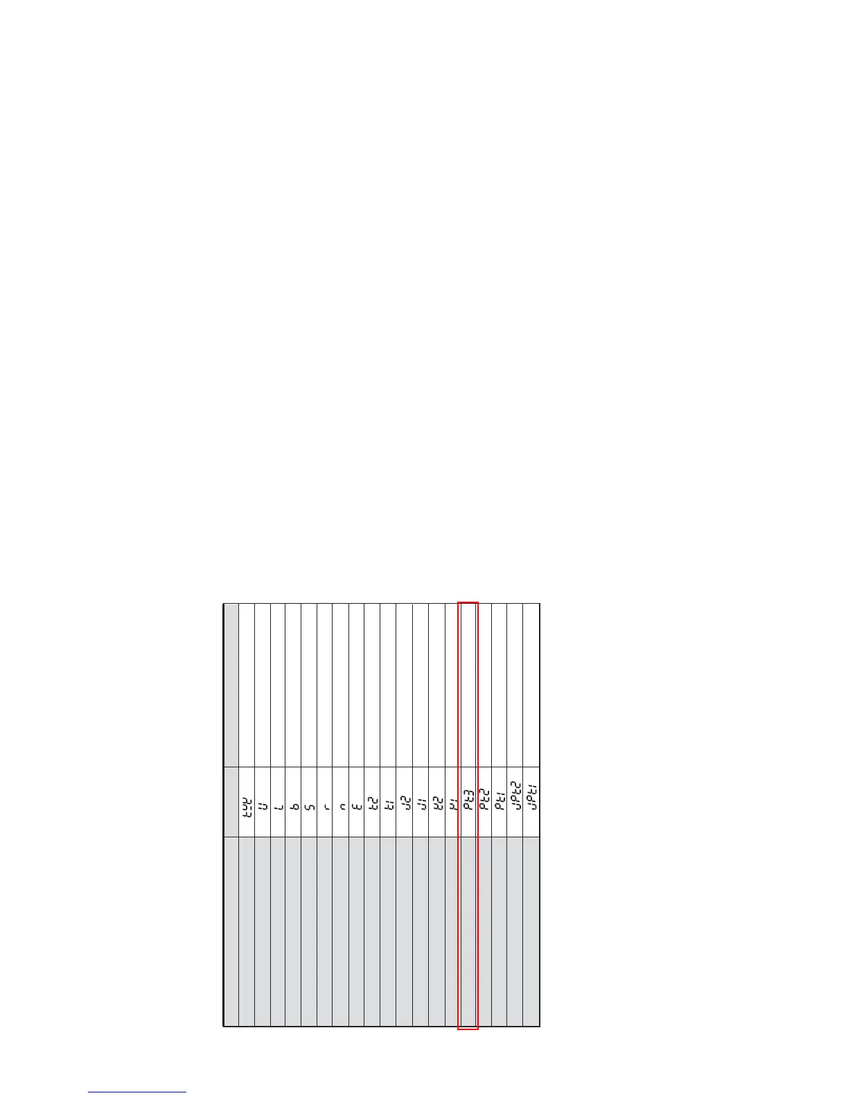
Input Selection. Select one of the following input types from
the below table.
Temperature Units. This parameter is only available for
thermocouple or RTD inputs.
Scale Height Limit. Sets the upper limit of the temperature
range. If the process temperature exceeds this setting, the
display will flash an error code.
Scale Low Limit. Sets the lower limit of the temperature range.
If the process temperature exceeds this setting, the display will
flash an error code.
Control Mode. Select method of control operation. Can be set
to PID, On-Off, or Manual.
Input Temperature Sensor Type LED Display Temperature Range
Thermocouple TXK type -328 ~ 1440°F (-200 ~ 800°C)
Thermocouple U type -328 ~ 932°F (-200 ~ 500°C)
Thermocouple L type -328 ~ 1562°F (-200 ~ 850°C)
Thermocouple B type 212 ~ 3272°F (100 ~ 1800°C)
Thermocouple S type 32 ~ 3092°F (0 ~ 1700°C)
Thermocouple R type 32 ~ 3092°F (0 ~ 1700°C)
Thermocouple N type -328 ~ 2340°F (-200 ~ 1300°C)
Thermocouple E type 32 ~ 1112°F (0 ~ 600°C)
Thermocouple T type2 -4 ~ 752°F (-20 ~ 400°C)
Thermocouple T type1 -328 ~ 752°F (-200 ~ 400°C)
Thermocouple J type2 -4 ~ 752°F (-20 ~ 400°C)
Thermocouple J type1 -148 ~ 1562°F (-100 ~ 850°C)
Thermocouple K type2 -4 ~ 932°F (-20 ~ 500°C)
Thermocouple K type1 -328 ~ 2340°F (-200 ~ 1300°C)
Platinum Resistance (Pt100) type 3 32 ~ 212°F (0 ~ 100°C)
Platinum Resistance (Pt100) type 2 -4 ~ 932°F (-20 ~ 500°C)
Platinum Resistance (Pt100) type 1 -328 ~ 1112°F (-200 ~ 600°C)
Platinum Resistance (JPt100) type 2 32 ~ 212°F (0 ~ 100°C)
Platinum Resistance (JPt100) type 1 -4 ~ 752°F (-20 ~ 400°C)
Page 13
in
t
Page 14
Heat/Cool Selection. Assigns output 1 to be either heat or
cool.
HEAt = Output 1 = Heating
CooL = Output 1 = Cooling
Alarm 1 Setting. Sets operation for Alarm 1. Please see
selection on Alarm Outputs for description of the outputs.
Alarm 2 Setting. Sets operation for Alarm 2. Please see
selection on Alarm Outputs for description of the outputs.
Communications Write Function Feature. Allows parameters
to be changed via the RS-485 communications. Setting to oFF
prevents any changes from remote users.
Controller Address: Set from 1 to 247. This value must match
the controller address used by the host computer.
Baud Rate Setting. This value must match the communication
baud rate of the host computer.
Communication Data Length. Choose either 7 or 8. This value
must match the communication data length of the host
computer.
Communication Parity Bit. Set this value to even, odd, or none.
This value must match the communication parity bit of the host
computer.
Communication Stop Bit. Set this value to 1 or 2. This value
must match the communication stop bit of the host computer.
ALA1
ALA2
CoSH
C-no
bP5
LEn
PrtY
StoP
 Loading...