1. Product Specification (continued)
1.3.2.4 Sync Signal Levels
The monitor must accept sync signals from both 3.3 and
5 volt TTL logic families.The inputs shall sense a logic 0
when the input is 0.8 volt or less and shall sense a logic 1
when the input is 2.0 volts or greater. In addition to these
level requirements, there shall also be a minimum of 0.3
volt hysteresis provided for noise immunity (typically by
using a Schmitt Trigger input ).That is , the input level at
which the monitor actually detects a logic 0 shall be at
least 0.3 volt lower than the level at which it actually
detects a logic 1.If the monitor sync processing circuits
are designed around the 3.3 volt logic family ,then the
sync inputs must be 5 volt tolerant .
TTL input loading shall be equivalent to one TTL input
load. When logic 0 is asserted by a sync input , the
maximum current source from any single monitor sync
input to the driver is 1.6 mA .When logic 1 is asserted ,
the maximum current source from the driver to any
single monitor sync input is 400 uA .
1.3.2.5 Sync Signal Loading
DSUB
Pin Signal Pin Signal Pin Signal
1
Red- Video
6
Red- GN D
11
GN D
2
Green-Video
7
Green-GN D
12
DDC-SDA
3
Blue-V ideo
8
Blue-G N D
13
H-SYN C
4
GN D
9
+5V
14
V-SYN C
5
DDC-GN D
10
Sync-GND
15
DDC-SC L
C o nnec to r P in As signm ent
D-SUB Pin Description
Pin N ame D e scription
1 Red- Video Red vi deo signal i nput.
2 Green- Vid eo Green video signal input.
3 Blue - V id e o Blue vid e o signa l inp ut.
4GND Ground
5 DDC - GND DDC ground for the VESA DDC2 Bi function.
6 Red- GN D Analog signal ground for the Red vi deo.
7 Green-GND Analog signal ground for the Green video.
8 Blue - G N D Ana log s igna l gr o und fo r the B lue vid eo .
9 +5V +5V input from host system for the VESA DDC 2Bi f uncti on.
10 Sync-GN D Signal ground
11 GN D Ground
12 DDC_S DA SDA signal input fo r the VESA DDCB2i function.
13 H-SYN C Horizontal signal input from the host system.
14 V-SYN C Vertical signal input from the host system.
15 DDC- SCL SCL signal input for the VESA DD C 2Bi function.
Connec tor P in Descriptio n
1.3.2 Video Input Signals
No. Symbol Item Min
Normal
Max Unit Remark
1
Fh Scanning H orizontal Frequency 31 69 kH z M inimum range
2
Fv Scanning V ertical Frequency 56 75 H z M inimum range
4
Vil Low Level Input 0 0.8 V Note 1)
5
Video RG B Analog V ideo L evel 0.0 0.7 1.0 V
75
Ω
to G round
N o te 1) S ch m itt- T rig ge rs In pu t , S up p o rte d 3 .3 V d e vic e H (& V ) sy nc o utp u t from P C .
Video Input Signal
1.3.2.1 Video Signal Amplitudes
The three video inputs consist of Red ,Green , and
Blue signals, each with its own coaxial cable
terminated at the monitor. These video signals are
analog levels, where 0 V corresponds to black ,
and 700 mV is the maximum signal amplitude for
the respective color, when each signal is
terminated by a nominal 75.0 ohms .For a given
monitor luminance levels are measured using this
defined video amplitud driving a monitor meeting
the termination requirements .The signal amplitude
is not to be readjusted to compensate for variations
in termination impendence.
1.3.2.2 Video Signal Termination Impedance
This analog video signal termination shall be 75
1% which shall be resistive with a negligible
reactive component
1.3.2.3 Synchronization ( Sync ) Signals
The Horizontal Sync (HS) TTL signal is used to
initiate the display of a horizontal line. HS may be
either active high or active low, depending upon
the timing .The Vertical Sync (VS) TTL signal is
used to initiate the display of a new frame .VS may
be either active high or active low, depending on
the timing
Ω
+/-
.
1.3.2.6 Abnormal Signal Immunity
The monitor shall not be damaged by improper
sync timing , pulse duration , or absence of sync ,
or abnormal input signal amplitude ( video and/ or
sync too large or too small) , or any other
anomalous behavior of a graphics card video
generator when changing modes , or when any
combination of input signals is removed or
replaced . Additionally , under these conditions ,
the monitor shall not cause damage to the driving
source
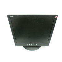
1.3.3 User Controls and Indicators
1.3.3.1 Power On / Off Switch
The monitor shall have a power control switch
visible and accessible on the front of the monitor .
The switch shall be marked with icons per IEC
417 , # 5007 and # 5009.The switch shall interrupt
the DC supply to the monitor
1.3.3.2 Power Indicator LED
The monitor shall make use of an LED type
indicator located on the front of the monitor .
The LED color shall indicate the power states as
given in Table 1.
Function LED Color
Full Power Green color
Sleep Amber color
Table 1
Go to cover page
3
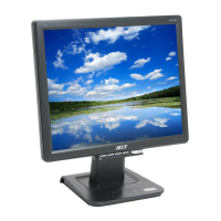
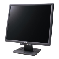
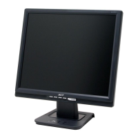
ACER AL1516W