EasyManua.ls Logo

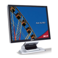
Acer AL1951 User Manual

Acer AL1951
52 pages
To Next Page IconTo Next Page
Page #1 background imageLoading...
Page #1 background image
Acer AL1951
Service Guide

Other manuals for Acer AL1951

Questions and Answers:

Acer AL1951 Specifications

General IconGeneral
BrandAcer
ModelAL1951
CategoryMonitor
LanguageEnglish

Summary

Service Guide Version and Revision

Copyright

Disclaimer

Trademarks

Conventions

Preface

FCC Certified Models Warning

Notice

Regulatory details on modifications, cables, and interference responsibility.

ENERGY STAR Compliance

Statement of product meeting ENERGY STAR guidelines for energy efficiency.

General Warning

Warning against exposure to rain, moisture, and high voltages.

Precautions

Special Notes on LCD Monitors

Normal LCD Monitor Symptoms

Explains normal symptoms like screen flicker, uneven brightness, dead/stuck pixels, and image retention.

Chapter 1 Monitor Features

Introduction

Defines requirements for the 19" LCD monitor, connectivity, and features.

Electrical Requirements

Details standard test conditions, control settings, and measurement systems.

LCD Monitor General Specification

Lists panel type, display size, resolution, clock, contrast, brightness, viewing angle, and interfaces.

LCD Panel Specification

Provides detailed specifications for the LCD panel, including resolution, pixel pitch, and weight.

Chapter 2 Machine Disassembly

Disassembly Procedure

Step-by-step instructions for disassembling the monitor for maintenance.

Chapter 3 Troubleshooting

No power

Flowchart for diagnosing and resolving power-related issues.

No picture (LED is orange)

Troubleshooting steps for issues where the monitor displays no picture with an orange LED.

Inverter Board

Troubleshooting steps for backlight issues related to the inverter board.

Chapter 4 Connector Information

15 – Pin Color Display Signal Cable (D-sub)

Pinout details for the D-sub monitor signal cable.

24 – Pin Color Display Signal Cable (DVI)

Pinout details for the DVI monitor signal cable.

Chapter 5 FRU (Field Replaceable Unit) List

Exploded Diagram (Model: AL1951)

Part List

Chapter 6 Schematic Diagram

TSU56AK SCHEMATIC

Detailed schematic of the TSU56AK chip and its connections.

POWER

Schematic diagram of the power supply section.

MPU

Schematic diagram of the Micro Processing Unit (MPU) circuit.

Related product manuals