Do you have a question about the Acer HARLEY TAB A3-A20 and is the answer not in the manual?
Statement regarding Acer Incorporated's warranties, software licensing, and limitation of liability for defects.
Guidance on checking the latest information for FRU parts via regional web or channel and potential part number changes.
Information for authorized providers regarding part number differences and the use of regional FRU lists for ordering.
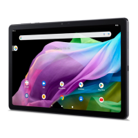
Summary of the tablet's main features, including form factor, OS, dimensions, weight, CPU, memory, LCM, storage, GPS, and camera specifications.
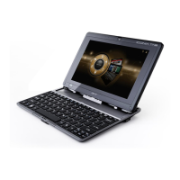
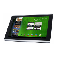
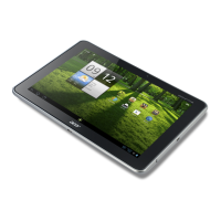
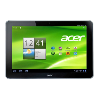
Visual overview of the tablet's external components and layout, showing six different views.
Detailed illustration and identification of components on the front of the tablet, including the touch screen and front camera.
Detailed illustration and identification of components on the rear of the tablet, including the rear cover module and rear camera.
Illustration and identification of components located on the top edge of the tablet, such as volume and power keys.
Illustration showing the bottom edge of the tablet, typically containing ports or speakers.
Illustration and identification of components on the left edge of the tablet, including various ports and keys.
Illustration of the right edge of the tablet, typically showing minimal components or a clean profile.
A schematic illustrating the internal components and their interconnections within the tablet.
Overview of the diagnostic tools available for software upgrading and writing device-specific codes like SN/IMEI.
Step-by-step instructions for using the Flash Tool to upgrade software, including opening the tool and downloading firmware versions.
Specifies the necessary hardware and software configurations for using the Writing Tool, including OS and required tools.
Guide on rewriting the country code using extension files in the WriteStation Tool for specific regions.
Procedure to access engineering mode and check the current Wi-Fi channel on the tablet.
General information on tablet maintenance, required tools, and procedures for component removal and installation.
Detailed, step-by-step instructions for safely disassembling and reassembling the tablet's internal components.
Troubleshooting procedures for common hardware faults, including boot failures, no ringtone, and display issues.
Overview of the Diagnostic Tool SOP, detailing its purpose for hardware testing by maintenance personnel.
Instructions for installing the diagnostic tool APK, including enabling developer options and USB debugging.
Covers the 15 diagnostic test items (Touch, LCM, Audio, etc.) and their main interface functions.
Details procedures for 15 tests including Touch, LCM, Back Light, Audio, Key, Vibration, G-sensor, SD/ExSD, Wifi, BT, GPS, OTG, Camera, Battery, HDMI.
Defines the structure and meaning of the 22-character Acer FG SN, including PN, Year, Week, and Sequence Number.
Explains the SNID format and calculation method based on Acer FG SN, including year, week, and sequence number.
Information on Acer FG labels, barcode standards (CODE-128), and label placement guidelines for ODMs.
Details the structure and definition of Acer KC PN and Acer KC SN, similar to FG SN but for KC components.
Visual representation of the tablet's exploded parts with item numbers for reference.
Detailed table listing all internal components with part names, descriptions, and quantities.
Categorized list of Field Replaceable Units (FRUs) with Acer Part Numbers and descriptions for ordering.
| Display Size | 10.1 inches |
|---|---|
| Resolution | 1280 x 800 pixels |
| RAM | 1 GB |
| Internal Storage | 16 GB |
| Rear Camera | 5 MP |
| Front Camera | 2 MP |
| Wireless | Wi-Fi 802.11 b/g/n |
| Bluetooth | Yes, v4.0 |
| Processor | Quad-core 1.3 GHz |
| Expandable Storage | microSD up to 32 GB |