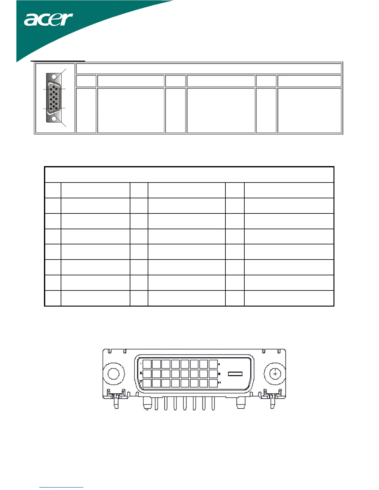
12
Pin Assignment
Signal
PIN Description PIN Description PIN Description
1
5
6
10
11
15
1
2
3
4
5
Red
Green
Blue
Digital GND
Digital GND
6
7
8
9
10
Red Rtn
Green Rtn
Blue Rtn
+5V
Hot Plug Detect
11
12
13
14
15
NC
SDA
H. Sync.
V. Sync.
SCL
Digital Video Input Connector : DVI – D (option)
Pin – Assignment of DVI –D connector :
1 TX2- 9 TX1- 17 TX0-
2 TX2+ 10 TX1+ 18 TX0+
3 Shield (TX2 / TX4) 11 Shield (TX1 / TX3) 19 Shield (TX0 / TX5)
4 NC 12 NC 20 NC
5 NC 13 NC 21 NC
6 DDC-Serial Clock 14 +5V power *) 22 Shield (TXC)
7 DDC-Serial Data 15 Ground (+5V) 23 TXC+
8 NC 16 Hot plug detect 24 TXC-
Pin assignment for DVI – D Connector (option):
 Loading...