Do you have a question about the Acer TravelMate 4100 and is the answer not in the manual?
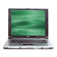
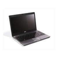
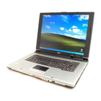
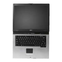
Overview of the computer's key design elements and capabilities.
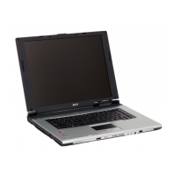
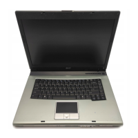
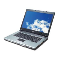
Visual guides to the computer's external component locations.
Details on keyboard layout, special keys, and touchpad functionality.
Information on audio capabilities and system management software.
Comprehensive technical data for all system components.
Accessing and navigating the BIOS setup utility.
Displays system information like CPU, memory, and BIOS version.
Allows configuration of system parameters and basic settings.
Provides advanced hardware configuration options.
Parameters for safeguarding the computer from unauthorized access.
Defines the order of devices for system startup.
Options to save, discard, or load default BIOS settings.
Required tools and important notes before starting disassembly.
A step-by-step visual guide to component removal order.
Step-by-step instructions for removing major computer parts.
Diagnostic tests to isolate hardware problems.
Troubleshooting steps for memory and power supply issues.
Interpreting error messages and POST codes for diagnosis.
Guidance for resolving intermittent, undetermined, and specific system issues.
Diagram showing connector locations on the motherboard's top side.
Diagram showing connector locations on the motherboard's rear side.
Identification of the Real-Time Clock jumper on the motherboard.
Visual breakdown of the computer's components for identification.
List of replaceable parts with their service part numbers.
| Processor | Intel Pentium M or Intel Celeron M |
|---|---|
| Chipset | Intel 915GM |
| Wireless LAN | 802.11b/g |
| Networking | Ethernet, Modem |
| Display Size | 15.0 inches |
| Display Resolution | XGA (1024 x 768) or SXGA+ (1400 x 1050) |
| Graphics | Intel Graphics Media Accelerator 900 |
| Operating System | Windows XP Professional |
| Battery | 6-cell Li-ion |
| Weight | 2.8 kg |
| Hard Drive Interface | IDE |
| Optical Drive | DVD-ROM |
| Audio | Built-in speakers and microphone |
| Ports | 3x USB 2.0, VGA, parallel, serial |