J
Justin ArroyoAug 5, 2025
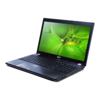
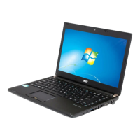
Why my Acer TravelMate 5730 Laptop doesn’t power off?
- AAnna ThompsonAug 5, 2025
If your Acer Laptop doesn’t power off, press and hold the power switch for more than 4 seconds.
Why my Acer TravelMate 5730 Laptop doesn’t power off?
If your Acer Laptop doesn’t power off, press and hold the power switch for more than 4 seconds.
Why does my Acer Laptop memory count appear different from actual size?
If the memory count size appears different from the actual size on your Acer Laptop, enter the BIOS Setup Utility to execute “Load Default Settings”, then reboot the system.
| Processor | Intel Core 2 Duo |
|---|---|
| RAM | Up to 4GB DDR2 |
| Resolution | 1280 x 800 |
| Graphics | Intel GMA 4500MHD |
| Operating System | Windows Vista Business |
| Wireless | 802.11a/b/g/n |
| LAN | Gigabit Ethernet |
| Card Reader | 5-in-1 card reader |
| Battery Life | Up to 3 hours |
| Storage | Up to 320GB HDD |
| Display | 15.4-inch |
| Optical Drive | DVD-Super Multi double-layer |
| Ports | 4 x USB 2.0, VGA, HDMI, ExpressCard/54 |
| Webcam | Integrated |
Details on computer features, platform, memory, display, graphics, and storage.
Identifies notebook parts, indicators, and special keys for user interaction.
Explains touchpad operation and keyboard functions, including hotkeys.
Introduces utilities for system management and optimization like Empowering Technology and e-Series.
Detailed technical specifications of the computer's hardware components.
Configuration program for managing system hardware and boot settings.
Guide on how to move through and interact with BIOS setup menus.
Details Information, Main, Security, Boot, and Exit screens within the BIOS utility.
Procedures for updating BIOS and managing system passwords.
Lists required tools and pre-disassembly instructions for safe component removal.
Step-by-step guide for removing external components like battery, drives, and memory.
Procedures for disassembling core internal components.
Instructions for removing parts like middle cover, keyboard, heatsink, CPU, and main board.
Detailed steps for disassembling the display assembly.
Guide on removing the LCD frame, mounting brackets, and associated cables.
Diagnostic steps for hardware issues with drives and input devices.
Procedures for testing memory modules and verifying power sources.
Explanation of POST error messages and interpretation of BIOS beep codes.
Guides for identifying failing parts and resolving intermittent or undetermined issues.
Identifies board connectors and provides steps for clearing passwords and recovering BIOS.
Visual breakdown and comprehensive list of replaceable parts.
Lists components verified for Windows Vista compatibility.