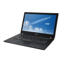
Do you have a question about the Acer TravelMate P633-M and is the answer not in the manual?
| RAM | 4 GB DDR3 |
|---|---|
| Storage | SSD or HDD (various capacities) |
| Graphics | Intel HD Graphics 4000 |
| Operating System | Windows 8 Pro / Windows 7 Professional |
| Processor | Intel Core i5-3210M |
| Display | 1366 x 768 |
| CPU | Intel Core i5-3210M |
Overview of the computer's hardware features.
Information about the CPU and chipset platform.
Specifications for system memory (RAM).
Details about the LCD display panel.
Specifications for the graphics controller.
Information on hard disk and SSD drives.
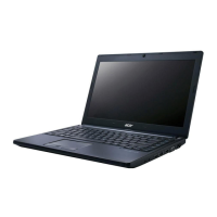
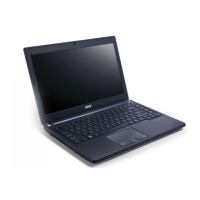
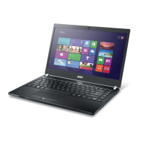
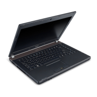
Overview of external and internal notebook components.
Identification of components visible when the notebook is open.
Identification of ports and connectors on the left side.
Identification of ports and connectors on the right side.
Identification of components on the bottom of the notebook.
Explanation of system status indicator lights.
Description of the keyboard features and layout.
Explanation of keyboard shortcuts for various functions.
Detailed technical specifications for computer components.
General physical and environmental specifications of the computer.
Specifications for the system board components.
Details about the CPU and its specifications.
Specifications and details about the system's BIOS.
Technical specifications for the hard disk drive.
Description of the meaning of various system LED indicators.
Guide to accessing and configuring system BIOS settings.
Description of the different BIOS setup utility menu tabs.
Procedures for updating the system BIOS firmware.
Procedures for removing HDD and BIOS passwords.
Steps to remove the hard disk drive password.
Information on using Desktop Management Interface tools.
Step-by-step instructions for disassembling and reassembling the notebook.
List of suggested tools for disassembly and maintenance.
Important steps to follow before starting disassembly.
General overview of the disassembly stages and procedures.
Steps for removing external components.
Procedure to remove the battery pack.
Procedure to remove the hard disk drive.
Procedure to remove the keyboard.
Steps for disassembling the main internal components.
Procedure to remove the system's main logic board.
Procedure to remove the CPU thermal module.
Procedure to remove the central processing unit.
Procedure to remove the display assembly.
Steps for disassembling the LCD assembly.
Procedure to remove the LCD bezel.
Procedure to remove the LCD panel itself.
Steps for reassembling the main internal components.
Procedure to replace the system's main logic board.
Procedure to replace the palmrest and upper case assembly.
Steps for reassembling external components.
Procedure to install the hard disk drive.
Procedure to install the battery pack.
Guidance on approaching computer problem diagnosis.
Steps to diagnose and resolve power-on problems.
Steps to diagnose and resolve display-related problems.
Troubleshooting steps when the system does not show POST or video output.
Steps to diagnose and resolve issues with the LCD screen.
Steps to diagnose and resolve keyboard malfunctions.
Steps to diagnose and resolve internal speaker issues.
Steps to diagnose and resolve microphone issues.
Steps to diagnose and resolve USB port or device issues.
Steps to diagnose and resolve wireless LAN connectivity problems.
Guidance for troubleshooting problems that occur sporadically.
List and explanation of common error codes.
Codes indicating status during the Power-On Self-Test.
Codes identifying specific hardware components during POST.
Diagrams showing the location of jumpers and connectors on the mainboard.
Identification of connectors and components on the top side of the mainboard.
Identification of connectors and components on the bottom side of the mainboard.
Procedures for clearing BIOS passwords and recovering BIOS.
Steps to clear lost BIOS user or supervisor passwords.
Instructions for recovering the BIOS from a corrupted state.
Exploded views of the main and LCD assemblies.
Exploded diagram of the main computer assembly with part numbers.
Exploded diagram of the LCD assembly with part numbers.
A comprehensive list of Field Replaceable Units and their part numbers.
List of components tested and verified for compatibility with Windows 7.
Details on accessing Acer's online technical support resources.
