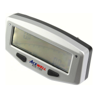
ATV/Motorcycle Computer
ACE-1500 User Manual
12
3
4
5 6
8
7
9
MADE IN TAIWAN
RESET
10R-029648
RESET
2-5
CDI
Ignion Coil
Tuns
RPM-INPUT
Either One
RPM sensing wiring Mounting
1. Signal intensity from ignion coil is dependent on vehicle type.
2. Circles 2-5 turns around ignion coil, with more turns creang
steadily stronger signal, fewer turns creang weaker signal.
3. The RPM circuit is designed for most bikes, however paral
bikes’signal is too strong if the RPM looks like much more
than actual RPM andunstable, please serial connect the
aached 1M Ohm resistor to solve it.
Max. 8mm
Vibration Direction
sensor
Max. 8mm
Vibration Direction
sensor
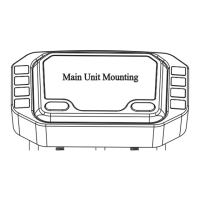
INSTALLATION & PARTS
Rubber Pad
Washer
Spring Washer
Fixing Screw Nut
Main Unit
Main Unit Mounting
Reed Speed Sensor and Magnet:
1. This sensor is universal sensor for motorcycle, find a
rotatable part to install magnet and a locaon can install
sensor and can be aligned to the magnet.
2. Align the center of the magnet to either of the sensor
marking lines or the side of the sensor.
3. Installing the sensor parallel to the vibraon direcon
creates oponal an-vibraon effect.
4. Make sure the gap between the magnet and the sensor
is within 8mm.
Speed Sensor Mounting
Acewell has several speed sensors; the unit includes one of them
or not speed sensor in case the model has to be connected to gear
box to get speed signal.
Thanks for bought the ATV/Motorcycle computer, please read the manual before you install the computer.
FEATURES
Displays bar-graphic tachometers, speedometer, bar fuel meter
and one addional funcon at the same me.
Powered with either the internal CR2032 baery or the bike’s
baery.
Bar-graph tachometers with selectable 10,000rpm or 20,000rpm
redline.
Allows end user to adjust odometer when the odometer is less
than 30km / 18.6 miles..
Fuel gauge includes +/-100, 250 and 510 Ohm opons for fuel
meter input resistance, as well as “fuel gauge off” mode..
Includes bracket, RPM sensing wire, speed sensor, fing kits
and wiring harness.
English
Power Input
Tachometer Sensor
Speed Sensor
Wheel circumference setting
Power Consumption
Dimensions
DC 12V
CDI or Ignition Coil Signal
Reed Sensor (Internal or Bike’s power) or
Hall sensor (Bike’s power application) only
1mm-3999mm
50uA at clock mode
1mA at on status without backlight and all sensors off
2mA at all sensors on status without backlight
15mA at on status with 3 sec backlight
25mA at on status with continue backlight
110.0mm x 55.0mm x 21.5 mm)
SPECIFICATIONS
Function Specifications
Simbolo
Bar Tachometer
500-10,000 rpm
1,000-20,000rpm options
Average speed 2.4-399.9 km/h (248.5 MPH)
AVG
100-19,900rpmDigital Tachometer
rpm
Speedometer 2.4-399.9 km/h (248.5 MPH)
km/H/MPH
Maximum speed 2.4-399.9 km/h (248.5 MPH)
MAX
Total Hour Meter 0-999999H
Riding Time 0-99H59`59``
Odometer 0 - 999999 KM, 0-62499 Miles
Trip meter 1&2 0.0-999.9 KM/Miles
Trip 1&2
12/24 Hour Clock 0:00`-11H59`/23H59`
Hour meter 0-9999H59`
Bar-Fuel Meter
+/-100Ω, 250Ω, 510Ω or OFF options
Maximum Tachometer MAX RPM 100-19,900rpm
1. Tachometer Scale
2. Bar Tachometer
3. 1st row: Current & Max.
Speedometer
4. 2nd row: Other funcons
PANEL DESCRIPTIONS
5. RESET Buon
6. MODE Buon
7. Bar Fuel Meter
8. RPM Warning Indicator
9. Fuel Gauge Warning LED
2015/05/14