EasyManua.ls Logo

aci AIM2 - User Manual

aci AIM2
8 pages
Print Icon
To Next Page IconTo Next Page
Loading...
Automation Components, Inc.
2305 Pleasant View Road | Middleton, WI 53562
Phone: 1-888-967-5224 | Website: workaci.com
Page 1
Version: 9.0
I0000585
FIGURE 1: DIMENSIONS
INTERFACE SERIES
Installation & Operation Instructions
AIM2
Phone: 1-888-967-5224
Website: workaci.com
GENERAL INFORMATION
The AIM2 optically isolates an analog (voltage
or current) input signal from its
corresponding output signal. It will accept
any input signal between 0 and 20 VDC, or 0
and 20 mA, and output any signal within
those ranges. The AIM2 has preset or
adjustable inputs and preset or adjustable
outputs that can be either voltage or current.
The current signals on the input or output can
be either sink or source. The AIM2 requires
one external 24 VAC isolation transformer
with oating secondary for power. It has an
onboard 24 VAC isolation transformer to
supply power to the isolated output. The
AIM2 is eld calibratable, however, factory
calibration is available upon request for an
additional charge. This will speed up
installation time for the end user.
MOUNTING INSTRUCTIONS
Ground yourself to discharge static electricity
before touching any electronic equipment, as
some components are static sensitive. The
interface device can be mounted in any position. If circuit board slides out of snap track, a non-conductive
stop” may be required. Use only ngers to remove board from snap track. Slide out of snap track or push
up against side of snap track and lift that side of the circuit board to remove. Do not flex board. Do not
use tools.
WIRING INSTRUCTIONS
PRECAUTIONS
• Remove power before wiring. Never connect or disconnect wiring with power applied.
When using a shielded cable, ground the shield only at the controller end. Grounding both
ends can cause a ground loop.
This device needs to have its own Isolated Transformer. This transformer cannot be
connected/or shared with any other device. It is recommended you use an isolated UL-listed class
2 transformer.
• All wiring must comply with all local and National Electric Codes.
I
4.60” (116.84mm)
3.23”
(81.90mm)
3.25”
(8255mm)
4.69” (119.13mm)
0.70”
(17.78mm)
Question and Answer IconNeed help?

Do you have a question about the aci AIM2 and is the answer not in the manual?

Overview

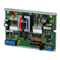
The AIM2 is an interface device designed to optically isolate an analog input signal (voltage or current) from its corresponding output signal. This isolation helps prevent ground loops and electrical noise from affecting the signal integrity. The device is versatile, accepting a wide range of input signals and producing a variety of output signals within those ranges.

Function Description:

The primary function of the AIM2 is signal isolation and conversion. It takes an analog input, which can be either a voltage (0-20 VDC) or a current (0-20 mA), and produces an isolated analog output within the same ranges. Both input and output signals can be configured as either voltage or current, and current signals can be set as either sink or source. This flexibility makes the AIM2 suitable for various industrial and building automation applications where signal integrity and isolation are crucial.

The device incorporates an onboard 24 VAC isolation transformer to supply power to the isolated output, ensuring true isolation between the input and output stages. An external 24 VAC isolation transformer with a floating secondary is required to power the AIM2 itself.

The AIM2 is field-calibratable, allowing users to fine-tune its performance to specific application requirements. Factory calibration is also available as an option for those who prefer a pre-configured device, which can expedite installation.

Important Technical Specifications:

  • Supply Voltage: 24 VAC (+/- 10%), 50/60 Hz
  • Supply Current: 200 mA maximum
  • Input Voltage Signal Preset Ranges: 0-5V, 0-10V, 0-15V, 0-20V, 1-5V, 2-10V, 3-15V, 4-20V, 0-1V
  • Input Current Signal Preset Ranges: 0-20 mA, 4-20 mA, 0-1 mA
  • Input Signal Adjustable Voltage Span: 1 VDC (Minimum) to 20 VDC (Maximum)
  • Input Signal Adjustable Voltage Offset: From 0 to 20 VDC
  • Input Signal Adjustable Current Span: 4 mA (Minimum) to 20 mA (Maximum)
  • Current Offset: From 0 to 20 mA
  • Input Voltage Impedance: 9,500Ω
  • Input Current Impedance: 250Ω +/-1%
  • Output Voltage Signal Preset Ranges: 0-5 VDC, 1-5 VDC, 0-10 VDC, 2-10 VDC
  • Output Current Signal Preset Ranges: 0-20 mA, 4-20 mA
  • Output Signal Adjustable Voltage Span: 1 VDC (Minimum) to 20 VDC +/- 1 VDC (Maximum)
  • Output Signal Adjustable Voltage Offset: From 0 to 10 VDC
  • Output Signal Adjustable Current Span: 0 mA (Minimum) to 20 mA (Maximum)
  • Output Signal Adjustable Current Offset: From 0 to 20 mA
  • Output Voltage Impedance: 5,000Ω
  • Output Current Impedance: 500Ω
  • Accuracy: +/- 3%
  • Linearity: +/- 1%
  • Connections: 45° Captive screw Terminal Blocks
  • Wire Size: 12 (3.31 mm²) to 22 AWG (0.33 mm²)
  • Terminal Block Torque Rating: 0.5 Nm (Minimum); 0.6 Nm (Maximum)
  • Operating Temperature Range: 35 to 120°F (1.7 to 48.9°C)
  • Operating Humidity Range: 10 to 95% non-condensing
  • Storage Temperature: -20 to 150°F (-28.9 to 65.5°C)
  • Dimensions: 4.60" (116.84mm) L x 3.23" (81.90mm) W x 0.70" (17.78mm) H (excluding snap track)

Usage Features:

  • Flexible Input/Output Configuration: The AIM2 supports a wide array of voltage and current input/output ranges, both preset and adjustable. This allows it to adapt to diverse control systems and sensor types. DIP switches and jumpers are used to configure these settings.
  • Voltage and Current Signals: The device handles both voltage (VDC) and current (mA) signals for both input and output.
  • Sink/Source Capability: For current signals, the AIM2 can be configured for either sink or source operation, providing compatibility with different current loop configurations.
  • Optical Isolation: The core feature of the AIM2 is its optical isolation, which breaks the galvanic connection between the input and output, preventing ground loops and protecting sensitive equipment from electrical disturbances.
  • Field Calibratable: Users can calibrate the input and output signals in the field to achieve precise measurements and control. This involves adjusting MIN and MAX pots and using a voltmeter to verify signal levels at designated test points (TP1 and TP3).
  • Snap Track Mounting: The device is designed for easy mounting in a snap track. It can be mounted in any position. Users are advised to use only fingers to remove the board from the snap track and avoid flexing the board or using tools to prevent damage.
  • DIP Switch and Jumper Settings: Configuration of input and output ranges, as well as direct or reverse acting output, is done via DIP switches and jumper blocks (J2, J3, J4, J5). Detailed tables are provided in the manual to guide users through these settings.
  • Shielded Cable Grounding: When using shielded cables, it is crucial to ground the shield only at the controller end to prevent ground loops.
  • Dedicated Isolated Transformer: The AIM2 requires its own dedicated isolated UL-listed class 2 transformer for power. It should not be connected to or share a transformer with any other device to maintain proper isolation and performance.
  • Compliance: All wiring must comply with local and National Electric Codes.

Maintenance Features:

  • Static Discharge Precautions: Before handling the device, users are instructed to ground themselves to discharge static electricity, as some components are static sensitive.
  • Power Disconnection during Wiring: It is critical to remove power before connecting or disconnecting any wiring to prevent damage to the device or injury.
  • Calibration Procedures: The manual provides detailed step-by-step instructions for calibrating both input and output signals, including procedures for preset and adjustable ranges, and for setting offsets and spans. This allows for ongoing accuracy and performance optimization.
  • Troubleshooting (Implicit): While not explicitly stated as "troubleshooting," the calibration steps and wiring precautions serve as a guide to ensure correct setup and operation, which inherently helps in preventing and resolving common issues.
  • Warranty: The AIM2 Series is covered by ACI's Two (2) Year Limited Warranty, details of which can be found in ACI's SENSORS & TRANSMITTERS CATALOG or on their website.

aci AIM2 Specifications

General IconGeneral
Brandaci
ModelAIM2
CategoryI/O Systems
LanguageEnglish