TABLE 1: VOLTAGE INPUT RANGE
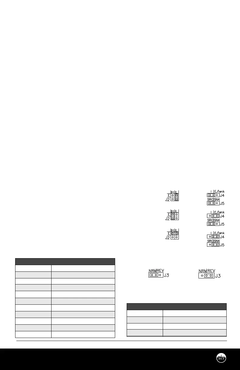
FIGURE 3: JUMPER SETTINGS
TABLE 2: CURRENT INPUT RANGE
Automation Components, Inc.
2305 Pleasant View Road | Middleton, WI 53562
Phone: 1-888-967-5224 | Website: workaci.com
Page 3
Version: 9.0
I0000585
INPUT DIP SWITCH
1, 6 ON………………… all others o
1,4,6 ON………………..all others o
1,5,6 ON………………..all others o
1,4,5,6 ON.....................all others o
1,7 ON………………….all others o
1,4,7 ON………………..all others o
1,5,7 ON………………..all others o
1,4,5,7 ON……………...all others o
2,6 ON………………….all others o
3,8 ON………………….all others o
3,4,5,8 ON……………..all others o
VOLTAGE INPUT
0 – 5 V
0 – 10 V
0 – 15 V
0 – 20 V
1 – 5 V
2 – 10 V
3 – 15 V
4 – 20 V
0 – 1 V
Adj. 1 – 9 V
Adj. 9 – 20 V
INPUT DIP SWITCH
1, 6 ON………………… all others o
1,7 ON………………..all others o
2, 6 ON………………..all others o
3, 8 ON.....................all others o
CURRENT INPUT
0 – 20 mA
4 - 20 mA
0 - 1 mA
Adj. 4 -20 mA
Figure A
Figure B
The AIM2 is factory set as follows, unless otherwise specied: All DIP switches are set to OFF and will not
produce a proper signal output. Be sure to set switches to your required input and output ranges before
powering. See “SETTING AIM2 INPUT” below.
The AIM2 can be eld calibrated to your specications using the “adjustable” setting on the DIP switches.
See “SETTING AIM2 INPUT” below.
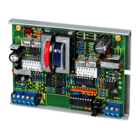
STEP 1) WIRING CONNECTIONS
With the power OFF, make the following connections:
Connect a 24 VAC power supply to the 24VAC terminals of the AIM2. Connect the input signal common (-)
to the COM input terminal of the AIM2, and the input signal positive (+) to the IN input terminal of the
AIM2.
Connect the output signal common (COM) and the output signal positive (OUT) to their respective
terminals on the controlled device.
SETTING AIM2 INPUT
DIP switches determine input ranges. Jumper block J2 is selectable for input voltage (E), current low 0 -
1mA (IL), or current high 0 – 20mA (IH) input signal. A current input can be either sinking or sourcing signal.
Explanation of “Source” and “Sink”:
Source – A signal where the positive (+) modulates and uses the negative (-) as the common. (Most
prevalent in the industry)
Sink – A signal where the negative (-) modulates
and uses the positive (+) as the common.
FOR PRESET VOLTAGE INPUT RANGES: Make
the following switch settings on input DIP switch.
Put Jumper J2 in (E) position (or Horz.) for voltage.
See Table 1.
FOR PRESET CURRENT INPUT RANGES: Make
the following switch settings on input DIP switch.
Put Jumper J2 in (IH) position for current. See
Table 2.
J2 Jumper Settings
For Inputs
J4 & J5 Jumper
Settings For Outputs
J3 Jumper Setting For Direct Or
Reverse Acting
Output
Source
Current
Voltage
Sink
Current
Direct
Acting
Reverse
Acting
0 - 1mA
(Sink or Source)
0 - 20mA
(Sink or Source)
Voltage
 Loading...