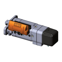
IT - INSTALLAZIONE DEL MOTORIDUTTORE A SINISTRA
Nella fig.6 e 7 viene mostrata la configurazione per l’installazione a sinistra del motoriduttore e della staffa di trasmissione.
EN - INSTALLATION OF THE MOTOR TO THE LEFT
Figures 6 and 7 show the configuration for the installation to the left of the geared motor and the transmission bracket.
IT - Per la configurazione a sinistra del motoriduttore procedere nel seguente modo: svitare l e 4 viti (D) mostrate nella figura 8 fino a liberare il
gruppo elettrofreno. Eseguire la rotazione di 180° del gruppo freno in modo tale che la catena, utilizzata per la manovra manuale, sia rivolta
perpendicolarmente verso il basso. A questo punto spingere il gruppo freno per vincere la resistenza della molla interna e procedere al
serraggio delle 4 viti precedentemente svitate. Attenzione: verificare che le 4 viti vadano ad i nserirsi correttamente nella scanalatura del
motore elettrico come mostrato nel dettaglio di figura 8. Tale operazione è fondamentale per il corretto funzionamento del gruppo elettrofreno.
Per la configurazione a sinistra della staffa di trasmissione procedere nel seguente modo: smontare il sistema paracadute dal perno (1) e
ruotandolo di 180°, montarlo sul perno (2) come mostrato in figura 9; Inserire la molla (M) tra i due fori ricavati rispettivamente sulla staffa e sul
sistema paracadute. A questo punto comprimer e il gruppo e fissarlo con l’anello seeger.
EN - For the configuration on the left of the gear motor, proceed as follows: Unscrew the 4 screws (D) shown in Figure 8 to release the electric
brake assembly. Rotate the brake assembly 180 ° rotation in such a way that the chain, used for the manual operation, is facing
perpendicularly downward. At this point push the brake assembly to overcome the resistance of the internal spring and proceed to tighten the
4 screws that were pr eviously loosened. Caution: verify that the 4 screws fit properly into the groove of the electric motor as shown in the
Figure 8 detail. This operation is essential for the proper functioning of the electric brake assembly.
For the configuration to the left of the transmission bracket, proceed as follows: Remove the parachute system from the pin (1) and turning it
180 °, mount it on the pin (2) as shown in Figure 9; Insert the spring (M) between the two holes for med respectively on the bracket and on the
parachute system. At this point, collapse the group and secure it with the snap ring.
IT - COLLEGAMENTI ELETTRICI
Collegare il cavo di alimentazione all’interno del finecorsa come illustrato in figura 10 rispettando la corretta disposizione dei cavi. Bloccare il
cavo di alimentazione serrando il premi-cavo (P). Collegare il cavo di terra alla staffa di trasmissione, come indicato nella figura 11.
EN - ELECTRICAL CONNECTIONS
Connect the power cable inside the limit switch as shown in Figure 10 with the proper cable arrangement. Lock the power cable by tightening
the cable-glands (P). Connect the earth cable to the bracket of transmission as indicated in Figure 11.
INSTALLAZIONE A SINISTR A DEL MOTORIDUTTORE CONFIGURAZIONE A SINISTRA DELLA STAFFA
Fig. 6 Fig. 7
INVERSIONE DEL GRUPPO FRENO – BRAKE SYSTEM INVERSION
INVERSIONE DEL SISTEMA PARACADUTE – PARACHUTE INVERSION
Fig. 8
Fig. 9
 Loading...