5. Control By Universal DMX Controller
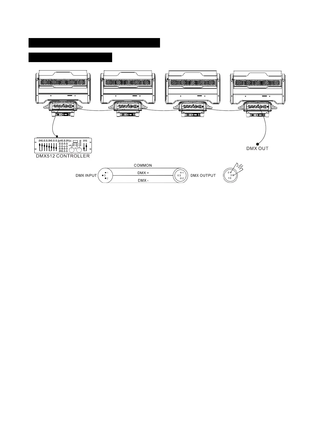
5.1 DMX512 Connection
1. At last unit, the DMX cable has to be terminated with a terminator. Solder a 120-o h m 1/4 W
resistor between pin 2(DMX-) and pin 3(DMX+) into a 3-pin XLR-plug and plug it in the DMX-output
of the last unit.
2. Connect the unit together in a “daisy chain” by XLR plug cable from the output of the unit to
the input of the next unit. The cable cannot be branched or split to a “Y” cable. DMX 512 is a very
high-speed signal. Inadequate or damaged cables, soldered joints or corroded connectors can easily
distort the signal and shut down the system.
3. The DMX output and input connectors are pass-through to maintain the DMX circuit, when one
of the units’ power is disconnected.
4. Each lighting unit needs to have a DMX address to receive the data by the controller. The
address number is between 1-512.
5. The end of the DMX 512 system should be terminated to reduce signal errors.
6. 3 pin XLR connectors are more popular than 5 pins XLR.
3 pin XLR: Pin 1: GND, Pin 2: Negative signal (-), Pin 3: Positive signal (+)
5 pin XLR: Pin 1: GND, Pin 2: Negative signal (-), Pin 3: Positive signal (+), Pin4, Pin5 not used.
18C