LED-CTL6
7-
C. By universal DMX controller
When using a universal DMX controller to control the chain of units, you have to set
DMX address by Dip switches from 1 to 9 to make sure all the units will receive its DMX
signal. Please refer to the following diagram to know how to address your DMX 512
system in the binary code.
DMX 512 Address Chart
Dip #1 #2 #3 #4 #5 #6 #7 #8 #9 #10
Value 1 2 4 8 16 32 64 128 256 M/S
• Examples:
Channel 1 : dip / on : #1 ( 1 )
Channel 5 : dip / on : #1, #3 ( 1+4 =5 )
Channel 9 : dip / on : #1, #4 ( 1 + 8 = 9 )
Channel 13 : dip / on : #1, #3, #4 (1+4+ 8 =13)
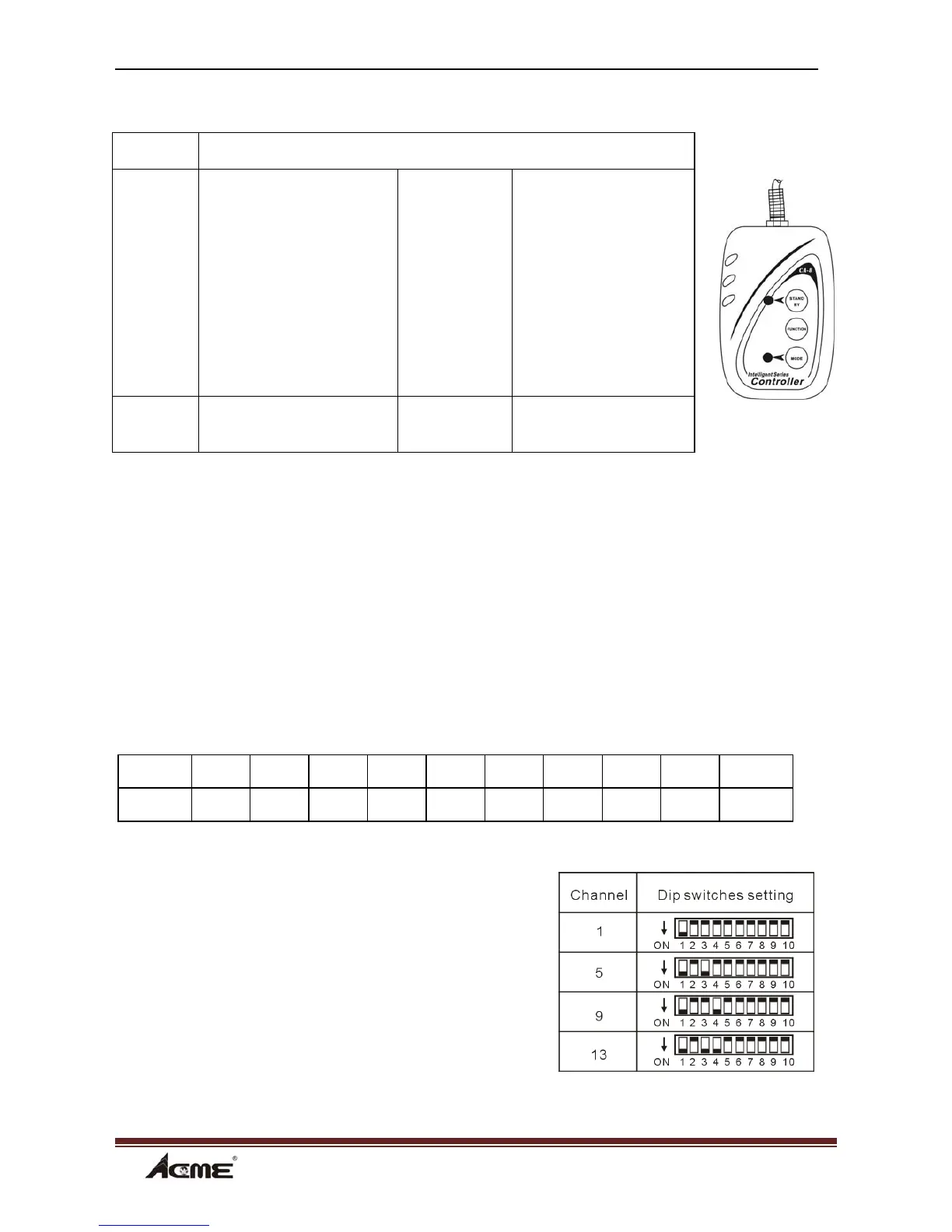
Blackout To blackout all the fixture
Function 1.Synchronous strobe
in white
2. Sound strobe
in white
3. Sound strobe
in color
Select color
1. Red
2. Green
3. Orange
4. Pink
5. Yellow
6. Cyan
7.Blue
8.Magenta
9.White
Select chase
1-6
Mode Sound 1
(LED OFF)
Manual
(LED ON)
Sound 2
(LED slow blinking)