INSTALLATION OF THE PANEL
Install the panel on building wall (vestibule, sheltered wall, east wall, etc.) so that to minimise the effect of
adverse weather conditions, especially water. Recommend installation height of the control panel is
approximately 1.35 m. The frame of the panel is installed with rawlplugs or appropriate screws, in addition
the frame for flush mounting is installed with plaster in wall cavity Lead the wires through the holes in the
base.
PLEASE NOTE! For proper operation and safety, connect the metal frame to earth by connecting the
grounding terminal with relevant protective installation (PE).
Use a 1.5 mm
2
cross-section cable (such OMY 2x1.5) with a maximum length of 30 m to connect the control
panel to power supply. Use a 1.0 mm
2
cross-section cable (such OMY 2x1.0) with a maximum length of 7 m
to connect the control panel to door E-lock. Insufficient power supply, too small cable cross-section and too
long connections (voltage drops) may cause interference in the operation of the device (such as interference
in the audio track: "buzzing" or reset system trip and device rebooting, especially when opening the E-lock).
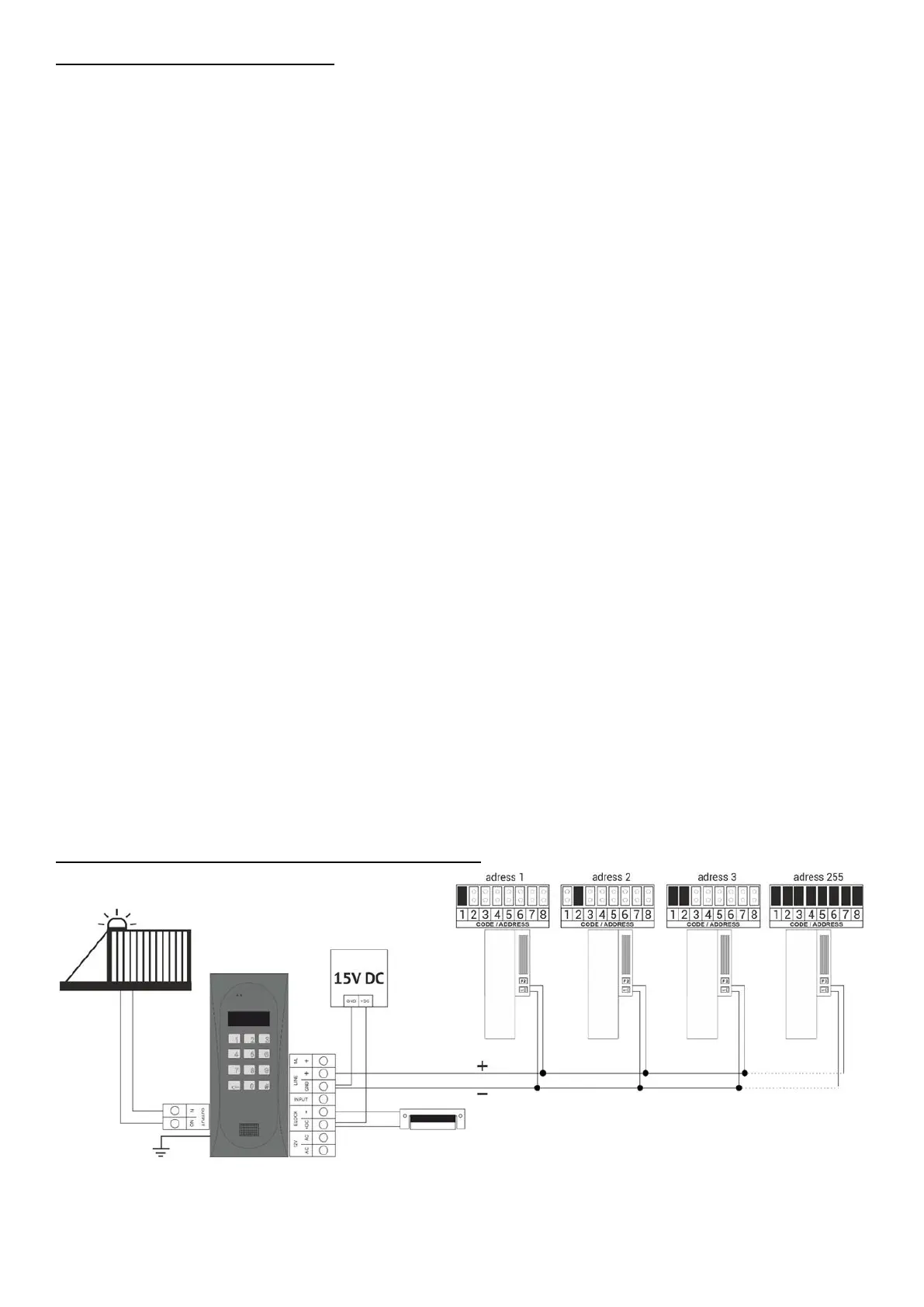
Use a +15VDC power supply to power the control panel, connected to the +DC (+ELOCK) and GND (LINE-
) terminals. When using an 11.5VAC (alternating voltage) power transformer, connect it to the 12V~AC/AC
terminals. For video systems, use only a 15V DC power supply and connect it to the terminals of the combiner.
Connect the E-lock with no specific polarity to "ELOCK" terminals, if a reversible E-lock is used, switch the
operation mode of the control panel to operation with a reversible E-lock (Program 17 Bit7). When using a
reversible E-lock, voltage appears at the "ELOCK" output depending on the power supply or used - use a
suitable reversible E-lock. It is also possible to use the MOD-DC-12V module for 12VDC power supply of
reversible E-lock if the door entry unit is supplied by a 15VDC power supply or a transformer. The additional
relay "OUTPUT" can be used to control the entrance gate for example (factory setting) using a code (with a
"double key") and the F2 button on the receiver. The response time (factory default is 1s) and functions of
the "OUTPUT" can be changed in program 18, port 2 (same as for the CND-I/O module). All connections
in the installation must be soldered!
Connect the following wires to the unit:
 Loading...