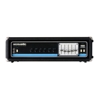
Do you have a question about the Acoustic 450 and is the answer not in the manual?
Stresses the necessity of registering the product within 10 days for warranty validation and service.
Explains the switch for lead vs. bass guitar modes and its effect on harmonics.
Describes circuit design providing constant power, good bass, and augmented harmonics.
Allows pre-setting two volume levels for switching with a foot switch.
Details voltage selection for international use via internal switches.
Describes the two input jacks, their loudness difference, and optimal usage for signal-to-noise ratio.
Explains how this switch boosts treble for a crisper sound.
Describes the volume control for all frequencies and functions.
Details the treble control for upper-range tones, its cut/boost type, and flat position.
Explains the mid-range control for middle tones, its cut/boost type, and use with Graphic EQ.
Describes the bass control for low-range tones, its cut/boost type, and use with Graphic EQ.
Explains the distortion control for creating fuzz effects, bypass, and foot switch operation.
Allows pre-setting two volume levels and switching between them with a foot switch.
Helps reduce or eliminate persistent hum or buzz from guitar strings.
Selects amplifier mode for lead or bass guitar, affecting harmonic response.
Turns the system on/off, with an indicator light and potential thump on power-up.
Explains the five-section graphic equalizer, its frequency ranges, and shaping capabilities.
Describes the two speaker output jacks and how to connect speakers.
Explains the booster output for driving additional power amplifiers and speakers.
Details the line output for controlling multiple amps/speakers from the preamp.
Describes the three-conductor jack for routing signal to/from accessory equipment.
Explains the connector for the distort and auxiliary volume footswitch.
Details the fuse location, type, and replacement guidelines for safety.
Describes the outlet for auxiliary power, warning about exceeding rating.
Discusses the grounding system of the line cord for shock prevention and hum reduction.
Lists physical connection types and quantities on the amplifier.
Details the types of potentiometers and switches used for amplifier controls.
Details continuous and peak power output ratings across different impedance loads.
Provides preamp, total, and power amp gain figures in dB and X multipliers.
Lists input voltage requirements for maximum output and input impedance.
Specifies the noise-to-full-output ratio under minimum and maximum volume conditions.
Outlines the amplifier's frequency response at 10W and power bandwidth.
Details output voltage and impedance for auxiliary and booster outputs.
Provides the minimum input voltage required to clip the power amp.
Lists the boost/cut ranges for Bass, Treble, Mid-Range, and Bright Switch.
Specifies the boost/cut ranges for each of the five graphic equalizer sections.
Details fuse and usage for 107V/110V supply lines, with caution for 120V.
Specifies fuse and usage for 117V/120V supply lines in the USA.
Details fuse and usage for 210V/220V AC supply lines, with caution for higher voltages.
Specifies fuse and usage for 225V/230V/240V AC supply lines in Europe/Australia.
 Loading...