Do you have a question about the ACP MenuMaster Commercial DEC11E2 and is the answer not in the manual?
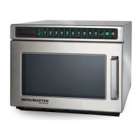
This document is a Service Training Manual for Menumaster Commercial Compact Microwave Ovens, specifically covering DEC-50Hz and CHDC-50Hz (Chinese Oven) models, with a publication date of September 2011 and part number 16400016. It provides comprehensive information for servicing and understanding these microwave ovens.
The manual begins with crucial safety information, emphasizing the importance of qualified service technicians and adherence to safety procedures. It highlights general warnings such as disconnecting power before servicing to avoid electrical shock and specific precautions related to microwave radiation. These include always operating the unit from a grounded outlet, performing a microwave leakage test before and after servicing, and never operating the oven if the door, hinges, choke, or seals are damaged. It also warns against defeating interlock switches and stresses that the oven should not be operated with removed or bypassed components or if safety interlocks are defective. All microwave ovens are designed to meet radiation control requirements, with a maximum leakage of 4mw/cm². If leakage exceeds this, servicing should cease, and ACP ComServ should be contacted. Further safety instructions cover avoiding fire hazards (e.g., not overcooking food, removing metal ties, not using the cavity for storage), and precautions for heating liquids to prevent sudden boiling over. It also advises against deep-fat frying, cooking eggs in their shell, or heating sealed containers in the oven.
Technical specifications for various models (DEC11E2, DEC14E2/CHDC5142, DEC18E2/CHDC5182, DEC21E2/CHDC5212) are detailed. These models operate on a 230V, 16A, 50Hz single-phase power source with a CEE 7/7 or CEE 7/7 CHINA plug configuration. Nominal microwave energy outputs range from 1100W to 2100W, with corresponding power consumptions from 2000W to 3100W. The operating frequency for all models is 2450 MHz. Minimum temperature rises range from 5.5°C (11°F) to 11.5°C (21°F). All models share the same cabinet dimensions: 419 mm (16.5") width, 343 mm (13.5") height, and 549 mm (21.6") depth. Cavity dimensions are 330 mm (13") width, 171 mm (6.75") height, and 305 mm (12") depth. Crated weights vary from 28 kg (62 lbs) to 34 kg (74 lbs), and uncrated weights from 25 kg (56 lbs) to 31 kg (68 lbs).
Installation guidelines include inspecting the oven for damage upon unpacking, removing all internal materials, and allowing the oven to warm up if stored in a cold area. To mitigate radio interference, users are advised to clean door and sealing surfaces, place the oven away from radios and televisions, and use a properly installed antenna.
The Quick Start Reference Guide outlines control panel functions, programming items, and user options. The "CLEAN FILTER" message indicates when the air filter needs cleaning, which should be done thoroughly, and the message will automatically clear after 24 hours. Users can set the filter cleaning frequency. Manual operation involves opening the door, placing food, entering cooking time via the "TIME ENTRY" pad, optionally setting power level with the "POWER LEVEL" pad (10% to 100%), and pressing "START." Preprogrammed pads allow for cooking with stored sequences. The X2 pad feature (on some models) doubles the cooking time of a preprogrammed sequence. Options like beep volume, single/double pad programming, and maximum cooking time can be customized by holding pad 2 for 5 seconds, selecting the option, and pressing the corresponding number pad to change the setting.
The components section provides exploded views and diagrams of the microwave oven's internal parts, including the touch panel, oven tray, tray support, grease shield, air filter, interlock switch assembly, triac, blower motor, diode bracket, capacitors, HV transformer, diodes, antenna motor, magnetrons, top and bottom antenna assemblies, shaft, washer, gear, control board, upper antenna motor, magnetron thermal cutout, and cavity thermal cutout. Special attention is drawn to high voltage components with "DANGER" warnings. The door assembly is shown in two styles: see-through and solid.
Disassembly instructions cover inner door/window removal and switch replacement/door adjustment. To remove the inner door/window, screws on the hinge side are removed, and a putty knife is used to pry up the inner door to release tabs. A caution warns to be careful when removing the glass retainer. For switch replacement, the old switch is removed, the new one is positioned, and screws are loosely installed before pushing and holding the assembly forward to tighten. Door adjustment involves loosening hinge bolts, lifting the door, clamping it, and tightening the bolts. Shims (12019302 and 12382602) are used for proper door alignment.
Capacitor/diode location diagrams are provided for different serial number ranges (prior to S/N 0902100848, starting S/N 0902100848, S/N 1103100152 and earlier, and S/N 1103100153 and after). These diagrams show the placement of capacitors and diodes, with specific notes on changes in flow divider removal for improved airflow in later models. "DANGER: High Voltage Components" warnings are reiterated in these sections.
Airflow diagrams illustrate how air circulates through the oven, emphasizing that the air filter must be in place and cleaned regularly.
Component testing procedures are detailed for various parts, including thermal cutouts, diode assemblies, triacs, capacitors, snubber assemblies, magnetrons, stirrer motors, and blower motors. Each component has specific tests (e.g., resistance measurements, voltage checks) and expected results. For instance, thermal cutouts should be open at specific temperatures, diode assemblies should show infinite resistance in one direction, and capacitors should momentarily deflect an ohmmeter then return to over 5 MΩ. A "WARNING" precedes this section, reminding technicians to disconnect power and discharge capacitors before testing. The manual also includes testing procedures for the transformer, interlock switch assembly (primary, monitor, secondary), touch panel assembly, and wire harness. Control board testing (Invensy and CPI) involves checking line voltage, output drive voltage to the triac, and fan/cook relay functions.
An error code table lists codes F1-F6 and their corrective actions, primarily involving replacing the HV/LV Board or Touch Panel. A "Usage Test" procedure allows access to Magnetron Hours, Magnetron Cycles, and Door Cycles by holding pad 3 for five seconds.
Troubleshooting flowcharts are provided for "Initial Power Up," "Standby Condition," and "Cook Condition."
The manual concludes with wiring diagrams and schematics for various models (DEC11E2 and DEC18E2 samples with CPI and Invensy Control, for different serial number ranges), illustrating the electrical connections and component layouts. These diagrams are crucial for diagnosing electrical issues.