Reverse this procedure for reassembly.
Be certain all set screws are tightened well and that all
keys have been replaced properly. It is suggested to deburr all keys before reassembly to
eliminate any possibility of binding.
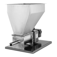
4.5.6 To remove the Metering Auger Drive Shaft (11)
, first remove the Metering Auger (10) and
Gear-reducer (2); please refer to paragraph 4.8. Then, loosen the set screws on Bearing (37) and
on Drive Gear (22). Remove Snap Rings (40)—when applicable. After this has been done, slide
the Metering Auger Drive Shaft (11) forward or backward to remove.
NOTE:
Loosening the Metering Auger Drive Shaft Seal Cap (14) will facilitate disassembly and
reassembly.
To reassemble, reverse the preceding procedure.
Verify that the seal Packing (16) has not
been damaged. Replace if necessary.
NOTE:
Certain Model 105 Feeders include Type PB Gearbox (3) assemblies which include a
Metering Auger Drive Shaft (11) with “Snap Ring” retainers (40) on the drive end to
prevent this shaft from moving under abnormal stress. Please note that it is not
necessary to remove the snap rings on the Metering Auger Drive Shaft (11) when
removing this shaft through the rear (drive side) of the gearbox. If the metering auger
drive shaft has been removed, during reassembly, be certain that the first snap ring is
flush against Bearing (37) before tightening the set screws on this bearing.
4.5.7 The Intromitter (or Conditioning Auger) Drive Shaft (9) must be removed as an assembly
with the Metering Auger Drive Shaft (11).
First, remove the Metering Auger (10), the
Conditioning Auger (8) and the Discharge Cylinder (12). Then, remove the Motor (1) and
Gear-reducer (2) as an assembly from the Gearbox (3) by loosening the set screws on the
hollow-shaft of Gear-reducer (2)—when applicable— and then, removing the four bolts which
secure the Gear-reducer (2) onto the Gearbox (3). Remove Snap Rings (40)—when
applicable—on the Metering Auger Drive Shaft (11).
After this has been done, loosen the set screws on Gear (22) and on Bearing (37). Then, loosen
the set screws on Gear (25), remove Snap Rings (41)—when applicable— on the Intromitter (or
Conditioning Auger) Drive Shaft (9), and loosen the set screws on Bearings (38). Once this has
been done, the Intromitter (or Conditioning Auger) Drive Shaft (9), with the Metering Auger Drive
Shaft (11) attached, can be pulled into the Conditioning Chamber (6) and removed.
To reassemble, reverse the preceding procedure.
When properly positioned, the flange of the
Conditioning Auger Drive Shaft (9) [against which the Conditioning Auger (8) seats] should be
about 3/16 to 1/4 inch away from the Seal Cap (15).
NOTE:
Snap Rings (41) may be included on the Intromitter (or Conditioning Auger) Drive Shaft
(9) to likewise ensure that this shaft does not move under abnormal stress (see Figure
2). When removing the Intromitter (or Conditioning Auger) Drive Shaft (9), the snap
rings on this shaft must first be removed. A snap ring tool is required to remove and
install snap rings.
4.5.8
If the Gearbox (3) must be removed, remove the bolts fastening the Seal Housing (5) to the
Conditioning Chamber (6) and the bolt fastening the Gearbox (3) to the Feeder Mounting Base
(4). Remove the Gearbox (3), Seal Housing (5) and Gear-reducer (2), with or without Motor (1), as
an assembly. Remove the Gear-reducer (2) and Motor (1) from the Gearbox (3), if necessary, as
previously outlined.
4.5.9
To replace any of the bearings within the Type PB Gearbox (3), follow the basic procedures as
outlined in the preceding in order to gain access to the applicable bearing(s). The bearings are
piloted to ensure proper and automatic realignment. Be certain to re-tighten all set screws and to
properly deburr and replace any keys and/or shafts which may have been removed.
14