-
Table of Contents
GENERAL INFORMATION 5
Intended Audience .................................................................................................................................. 5
Preface ..................................................................................................................................................... 5
Trademark, Trade Name and Copyright Information 5
Radio Frequency Interference Statement .......................................................................................... 5
Environmental Protection Statement 5
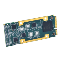
AP560A OVERVIEW .................................................................................................................................. 5
Ordering Information .............................................................................................................................. 6
KEY FEATURES .......................................................................................................................................... 6
AcroPack Module Interface Features ...................................................................................................... 7
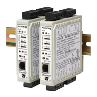
Signal Interface Products ......................................................................................................................... 7
Software Support..................................................................................................................................... 7
Windows 7
VxWorks 7
Linux 8
1. PREPARATION FOR USE 9
UNPACKING AND INSPECTION ................................................................................................................ 9
Installation Considerations ...................................................................................................................... 9
CONNECTORS ........................................................................................................................................ 10
Field I/O Connector P2 10
Logic Interface Connector 15
2. PROGRAMMING INFORMATION 17
PCIe Configuration Address Space ........................................................................................................ 17
Configuration Registers ......................................................................................................................... 17
MEMORY MAP ....................................................................................................................................... 18
CAN Registers 19
Channel Busy Register, (Read) - (Base + 08H) 19
Channel x Command Register, (Read/Write) - (BAR0 + Chan X base + 00H) 20
Channel x Control Register, (Read/Write) - (BAR0 + Chan X base + 04H) 20
Channel x Output Message Registers, (Read/Write) - (BAR0 + Chan X base + 10H thru 1CH) 21
Channel x Input Message Registers, (Read/Write) - (BAR0 + Chan X base + 20H thru 2CH) 21
Interrupt Controller 21
Interrupt Status Register 22
Interrupt Pending Register 23
Interrupt Enable Register 23
Interrupt Acknowledge Register 24
Set Interrupt Enable Register 24
Clear Interrupt Enable Register 25
Interrupt Vector Register 25
Master Enable Register 25
AXI XADC Analog to Digital Converter (System Monitor) 26