Do you have a question about the Acson A5WMX 10 GR and is the answer not in the manual?
Total energy saved can be as high as 30% compared to conventionally controlled units.
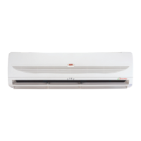
ACSON DC Inverter series achieve excellent efficient with high EER & COP rating.
Users enjoy better comfort and quietness with inverter technology.
Introducing the new type of refrigerant - R410A which is environmental friendly.
Incorporating fuzzy logic control into the ACSON Inverter design enables greater flexibility.
Both indoor and outdoor LED Error Code Indicator helps to simplify the trouble shooting process.
The compact LCD transmitter is able to operate the air conditioner unit within the distance of 9 meters.
Provides general specifications for indoor and outdoor units, including cooling/heating capacity and power.
Details the functions and operation of the G12 remote controller with button descriptions.
Guidelines for selecting appropriate locations for indoor and outdoor units to ensure optimal performance.
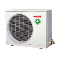
Specifies minimum distances required around outdoor units for proper airflow and maintenance.
Instructions on drilling holes and securely mounting the installation plate for the unit.
Details on preparing the indoor unit for refrigerant piping routing and electrical connections.
Step-by-step guide on how to hook and mount the indoor unit onto the installation plate.
Ensures proper downward gradient for indoor unit drain pipe for smooth water drainage.
Instructions for proper disposal of condensed water from the outdoor unit, especially for heat pump models.
Provides information on power supply cable size, number of wires, and recommended fuses.
Details maximum pipe length, elevation, bends, and pipe sizes for refrigerant connections.
Instructions on cutting pipes and preparing them for flare connection.
Steps for aligning piping and tightening flare nuts using torque wrench.
Explains R410A as an HFC refrigerant that does not damage the ozone layer.
Details the mixture weight composition of R410A as R32 (50%) and R125 (50%).
Discusses R410A's properties, including composition changes with phase and POE oil usage.
Provides a checklist of essential items and tools required before installation or servicing.
Outlines precautionary measures for handling R410A systems, emphasizing moisture control and vacuuming.
Guidance on charging R410A, ensuring liquid withdrawal for correct composition.
Instructions for withdrawing R410A from cylinders, with or without a dip pipe.
Procedure for air-purging indoor units and refrigerant connection pipes before charging.
Information on calculating and adding refrigerant based on piping length.
Step-by-step process for charging refrigerant using a gas cylinder and weighing machine.
Maintenance procedures and period for cleaning indoor air filters.
Cleaning procedures for indoor unit grille/panel and general unit care.
Instructions for checking and cleaning the condensate drain pan and pipe.
Procedure for checking the indoor fan for unusual noise.
Checks for dirt, obstacles, and general maintenance of indoor and outdoor coils.
Maintenance checks for voltage, current, wiring, and faulty contacts in electrical components.
Checks for refrigerant leaks at joints and fittings if the refrigerant circuit remains sealed.
Information regarding compressor lubrication and oil requirements.
Notes that fan motors are pre-lubricated and sealed at the factory.
Troubleshooting steps for delayed startup after power failure or restart.
Steps to address the compressor not operating within 3 minutes of starting.
Troubleshooting for low airflow or insufficient cooling, including filter checks.
Addressing bad odors from discharge air, possibly due to coil contamination.
Explanation for condensation on the indoor unit's front grille.
Troubleshooting water leakage from the unit, possibly due to installation tilt.
Possible causes for hissing sounds during operation, related to refrigerant flow.
Guidance on interpreting blinking LED indicators on the indoor unit.
Troubleshooting when the outdoor unit is inoperative and indoor LED is not blinking.
Explains the beep signal from the indoor unit's IR receiver for remote control confirmation.
Describes LED indicator lights for normal and fault conditions on cooling/heatpump units.
LED indication for normal cooling mode operation.
LED indication for normal heat mode operation.
LED indication for automatic cooling/heating operation.
LED indication when the timer function is active.
LED indication when the sleep mode is activated.
LED indication when the ionizer function is active.
LED indication for normal fan mode operation.
LED indication for normal dry mode operation.
LED indication showing the unit is currently in defrost mode.
Fault indication for indoor temperature sensor issues, requires dealer contact.
Fault indication for coil temperature sensor issues, requires dealer contact.
Fault indication for outdoor temperature sensor issues, requires dealer contact.
Indicates compressor overload protection has been activated.
Error indication related to IPM or PFC module, requires dealer contact.
Indicates trip due to outdoor total current or DC peak.
Indicates compressor overheat or a gas leak in the system.
Fault indication for the indoor fan feedback system, requires dealer contact.
Indicates a communication failure between the indoor and outdoor units.
Troubleshooting for outdoor ambient sensor errors, check wire and connection.
Troubleshooting for outdoor coil sensor errors, check wire and connection.
Troubleshooting discharge sensor error or compressor overheat.
Troubleshooting DC compressor feedback issues, contact dealer.
Troubleshooting communication errors between units, check interconnection wire.
Troubleshooting over current faults, check compressor wire and connection.
Troubleshooting no load conditions, check power supply.
Troubleshooting over/under voltage issues, contact dealer.
Troubleshooting DC compressor start failure, contact dealer.
Troubleshooting cooling overload, check for unit blockage.
Guidance on defrost operation, wait for it to complete before restarting.
Troubleshooting IPM protection errors, check IPM.
Troubleshooting EEPROM read errors, requires EEPROM change.
Troubleshooting EEPROM write errors, requires EEPROM change.
Troubleshooting DC fan motor feedback errors, check motor wire connection.
Troubleshooting AC peak current errors, contact dealer.
Troubleshooting outdoor suction sensor errors, check wire and connection.
Troubleshooting DC compressor speed control errors, contact dealer.
Troubleshooting outdoor suction A sensor errors, check wire and connection.
Troubleshooting outdoor suction B sensor errors, check wire and connection.
Troubleshooting outdoor suction C sensor errors, check wire and connection.
Troubleshooting outdoor suction D sensor errors, check wire and connection.
Troubleshooting indoor A communication errors, check interconnection wire.
Troubleshooting indoor B communication errors, check interconnection wire.
Troubleshooting indoor C communication errors, check interconnection wire.
Troubleshooting indoor D communication errors, check interconnection wire.
Indicates normal operation of the unit without any limitations.
Indicates the unit is operating under voltage limit conditions.
Indicates cooling operation is limited by outdoor coil temperature.
Indicates the unit is operating under total current limit.
Indicates the unit is operating under discharge temperature limit.
Indicates cooling operation is limited by indoor coil temperature.
Indicates the indoor fan is under control or adjustment.
Indicates outdoor unit frequency is being adjusted.
| Type | Wall Mounted |
|---|---|
| Refrigerant | R32 |
| Power Consumption (Cooling) | 0.81 kW |
| Noise Level (Indoor) | 38 dB(A) |
| Cooling Capacity | 9, 500 Btu/h |
| Power Supply | 220-240V, 50Hz |