1-3
English
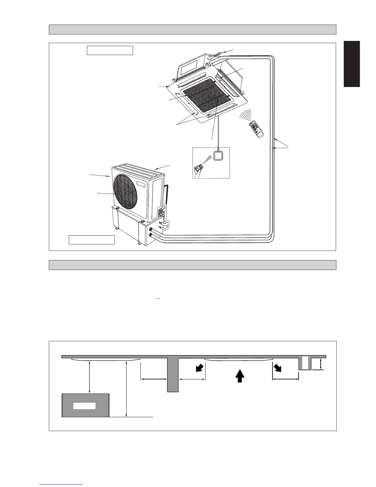
INSTALLATION DIAGRAM
Drain Hose
Front Panel
Air Filter
(behind the grille)
Air Discharge Louver
IR Receiver
LED Light
Water Piping
Air Intake
Air Discharge Nozzle
Air Intake
Preliminary Site Survey
• Electrical supply and installation is to conform to local authority's (e.g. National Electrical Board) codes and regulations.
• Voltage supply fluctuation must not exceed
+
10% of rated voltage. Electricity supply lines must be independent of welding
transformers which can cause high supply fluctuation.
• Ensure that the location is convenient for wiring, piping and drainage.
• The indoor unit must be installed in such that is free from any obstacles in path of cool air discharge and warm air return,
and must allow spreading of air throughout the room (near the center of the room).
• Must be provide clearance for the indoor unit from the wall and obstacles as shown in the figure.
• The installation place must be strong enough to support a load 4 times the indoor unit weight to avoid amplifying noise and
vibration.
• The installation place (handing ceiling surface) must be assuring levelness and the height in the ceiling is 350 mm or more.
• The indoor unit must be away from heat and steam sources (avoid installing it near an entrance).
INSTALLATION OF INDOOR UNIT
Max. 0.3 m
Min. 0.5 m
Min. 0.5 m
Min. 0.5 m
Min. 1.0 m
Max. 3.0 m
Floor
Obstacle
Beam
Outdoor Unit
Indoor Unit
Wireless
Remote Control
or
Wired Remote Control
Netware - 2
or
SLM - 3
Air Intake Grille