24
AWM-G-2009 Application Information
Wiring
Electrical Connection
Wiring regulation on wire diameters differ from country to country. Please refer to your LOCAL
ELECTRICALCODES for fi eld wiring rules. Be sure that installation comply with such rules and regulations.
General Precautions
Ensure that the rated voltage of the unit corresponds to the name plate before carrying out proper
wiringaccording to the wiring diagram.
Provide a power outlet to be used exclusively for each unit. A power supply disconnect and a circuit
breakerfor over current protection should be provided in the exclusive line.
The unit must be GROUNDED to prevent possible hazards due to insulation failures.
All wiring must be fi rmly connected.
All wiring must not touch the hot refrigerant piping, compressor or any moving parts of fan motors.
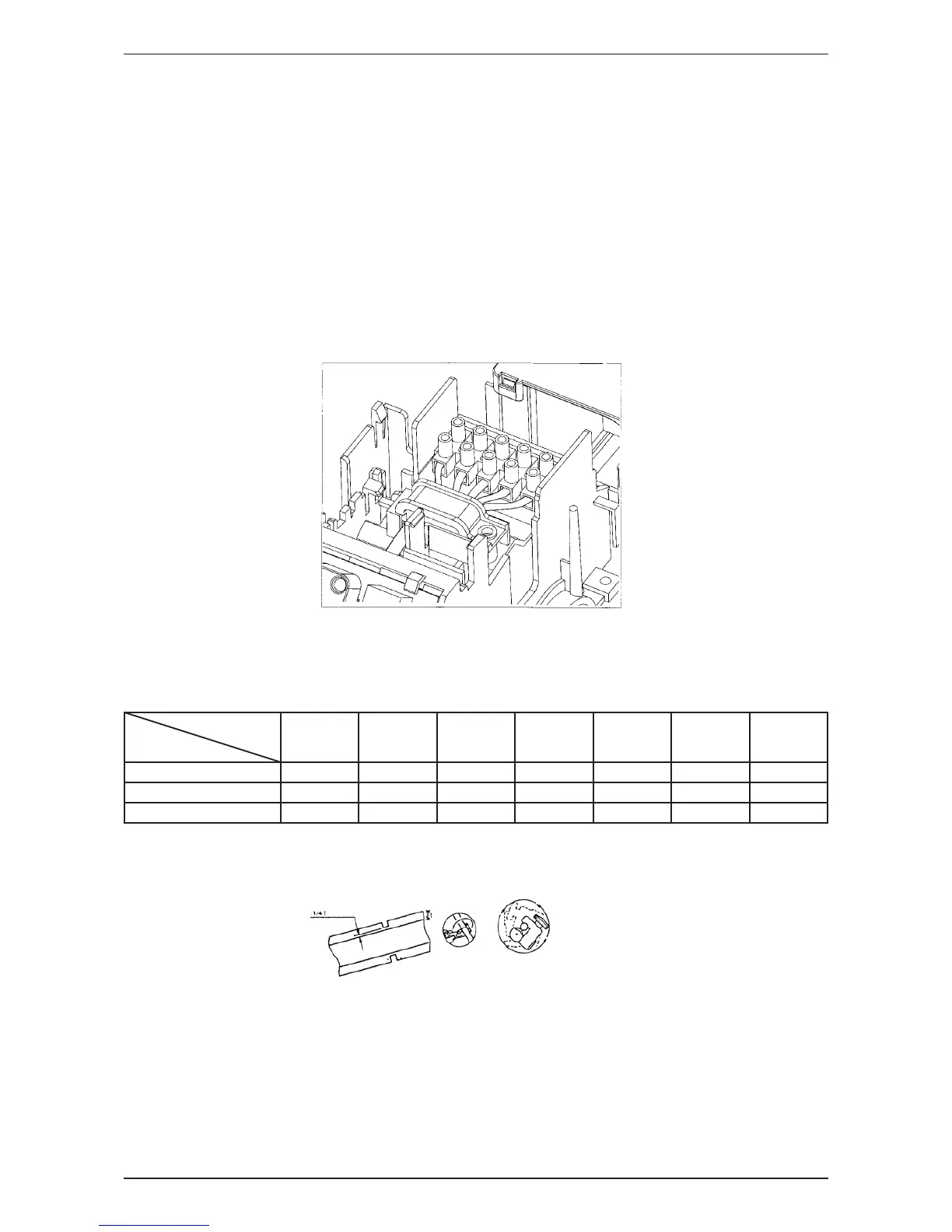
The fi eld wires from the indoor unit must be clamped on the wire clamp as per shown in the fi gure.
Refrigerant Piping
Maximum pipe Length and Maximum Number of Bends
Always choose the shortest path for refrigerant piping and follow the recommendations as tabulated below:
Model
AWM/A5WM
07G/GR
AWM
09G/GR
AWM/A5WM
10G/GR
AWM/A5WM
15G/GR
AWM/A5WM
20G/GR
AWM/A5WM
25G/GR
A5WM
311/301R
AWM 301/R
Data
Max. Length, L (m) 12 12 12 12 15 15 15
Max. Elevation, H (m) 5555888
Max. No. of Bends 10 10 10 10 10 10 10
Flare Connection
Cut the pipe stages by stages, advancing the blade of pipe cutter slowly.
Remove burr with the burr remover. Hold the fl aring end down to prevent burrs from dropping inside pipe.
•
•
•
•
•
•
•
•
•
 Loading...