1-8
Wire connection to the controller board is as show in the wiring diagram on the respective terminal box.
The standard controller board comes with a VALVE jumper and a HEAT jumper. The system must be configurated as the
jumper selection listed below:
HEAT Jumper VALVE Jumper
Cooling Mode & Valve Application x
P
Cooling Mode & Valveless Application x x
Heatpump Mode & Valve Application
PP
Heatpump Mode & Valveless Application
P
x
Example: If the unit is running “Heatpump Mode & Valveless Application”, remain the HEAT jumper while remove the
VALVE jumper.
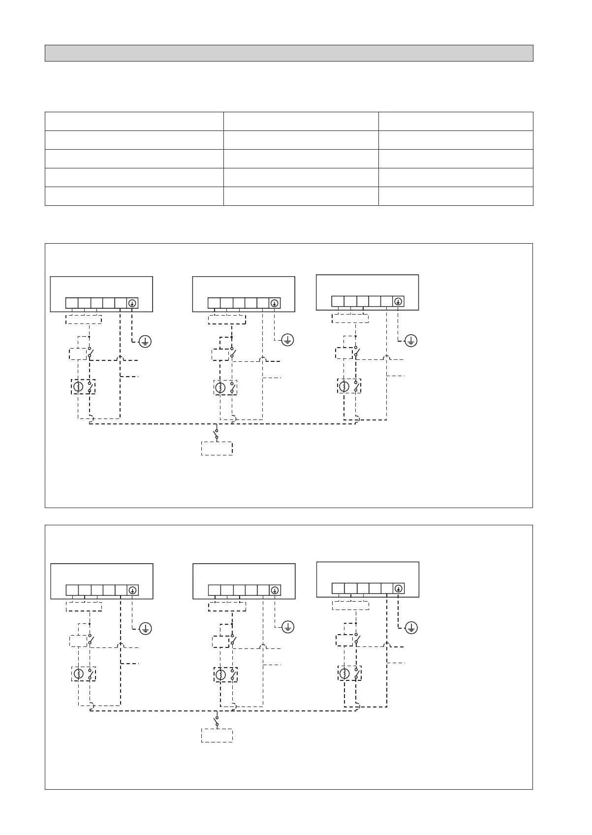
CC10CW / 15CW / 20CW / 25CW (without controller)
FCU 1 FCU 2 FCU 3
FSC
X2
X1
Chiller
FL FM FH L N
!
There must be an all pole
disconnection in the supply
mains with a contact separation
of at least 3mm.
All power line must be from
the same phase.
ELECTRICAL WIRING CONNECTION
TH
220-240V/1ø/50Hz or
208-230V/1ø/60Hz
TH
X3
220-240V/1ø/50Hz or
208-230V/1ø/60Hz
220-240V/1ø/50Hz or
208-230V/1ø/60Hz
TH
FSC
FSC
FL FM FH L N
FL FM FH L N
L
N
L
N
L
N
FL Fan Low
FM Fan Medium
FH Fan High
L Live
N Neutral
FSC Fan Speed Controller
X1, X2, X3 Relay (220 ~240V, 10A)
TH Thermostat
FCU 1 FCU 2 FCU 3
FSC
X2
X1
Chiller
SH H M L N
TH
220-240V/1ø/50Hz or
208-230V/1ø/60Hz
TH
X3
220-240V/1ø/50Hz or
208-230V/1ø/60Hz
220-240V/1ø/50Hz or
208-230V/1ø/60Hz
TH
FSC
FSC
SH H M L N
SH H M L N
L
N
L
N
L
N
SH Fan Super High
H Fan High
M Fan Medium
L Fan Low
N Neutral
FSC Fan Speed Controller
X1, X2, X3 Relay (220 ~240V, 10A)
TH Thermostat
CC28CW / 30CW / 38CW / 40CW / 50CW / 60CW (without controller)
!
There must be an all pole
disconnection in the supply
mains with a contact separation
of at least 3mm.
All power line must be from
the same phase.
1 IM-CCCW-1100(4)-EN.indd 81 IM-CCCW-1100(4)-EN.indd 8 12/3/13 12:20:15 PM12/3/13 12:20:15 PM
 Loading...