1-6
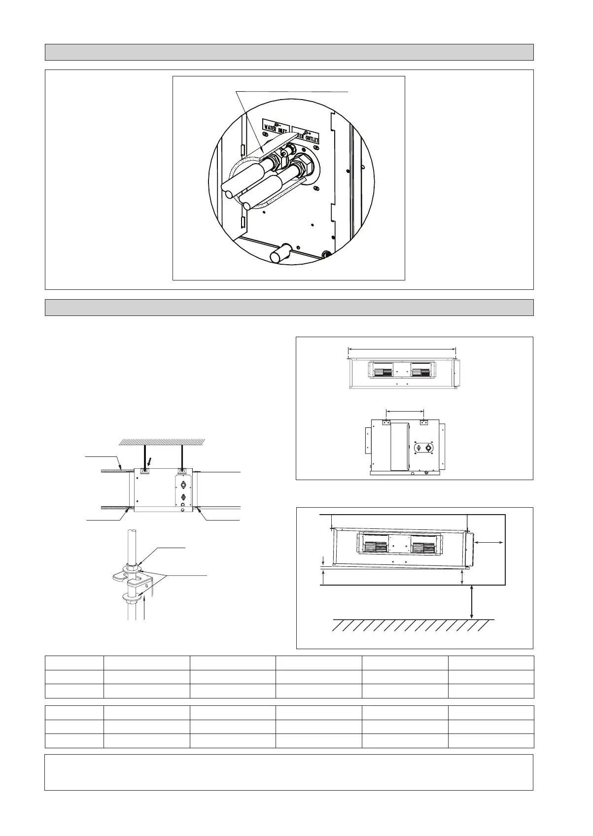
CORK TAPE FULLY INSULATED
INSULATION THROUGH OUT CHILLED WATER PIPING
The indoor unit must be installed such that there is no short
circuit of the cool discharge. Respect the installation clearance.
Do not put the indoor unit where there is direct sunlight on unit.
The location is suitable for piping and drainage and it must have
a large distance between a door and unit.
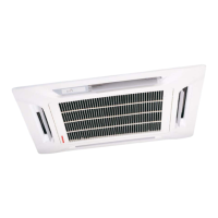
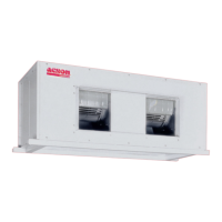
Ceiling Concealed Mounting
Use the hanger supplied with the unit.
Make sure that the ceiling is sufficiently strong to withstand
the weight.
•
•
Center distance of axle (see drawing below)
Provide clearance for servicing ease and optimal air flow as
shown in the diagram.
INSTALLATION DIAGRAM
INSTALLATION OF THE INDOOR UNIT
! CAUTION
Do not install the unit at altitude over 2000m for both indoor and outdoor.
A
L
300mm* or more
300mm
or more
10mm
* Can be smaller than 300mm if ceiling is removable.
Floor
2300mm or more
Ceiling
CC CC10CW CC15CW CC20CW CC25CW CC28CW
A (mm) 741 881 1041 1176 959
L (mm) 225 225 225 225 339
CC CC30CW CC38CW CC40CW CC50CW CC60CW
A (mm) 956 1264 1076 1326 1526
L (mm) 266 401 266 266 266
Insulation material
(field supply)
Aluminium tape
(field supply)
Aluminium tape
(field supply)
Air outlet side
Air inlet side
See
Detail A
Field supply
Washer for hanger bracket
(attached)
Tighten
Detail A
1 IM-CCCW-1100(4)-EN.indd 61 IM-CCCW-1100(4)-EN.indd 6 12/3/13 12:20:14 PM12/3/13 12:20:14 PM