Hardware Manual
23
How to Connect a Serial Device
The camera can be connected to a Pan-Tilt (PT) Scanner (Pan-Tilt Head) using the serial port
connector. This allows the zoom camera to do pan and tilt using the Pelco-D protocol. Most PT
scanners accept Pelco-D and Pelco-P protocol commands via RS-485 connection, which are
both supported by your camera.
Check the connection available on the PT scanner and connect it to your camera following the
procedures below.
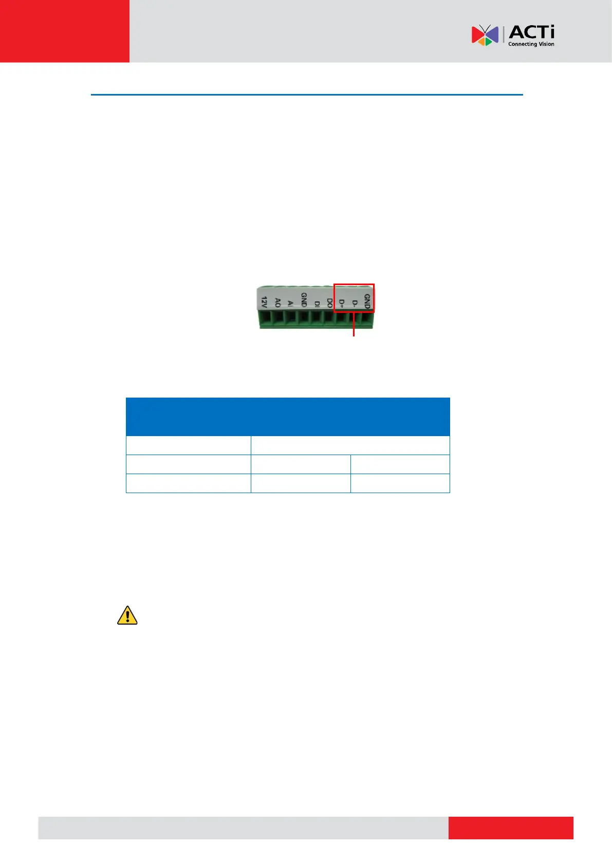
1. Map the wires from the PT scanner to your camera using the supplied terminal block
according to the table below.
Via RS-485 Connection
NOTE: The pins of the PT Scanner may be labeled differently depending on the location or
country where the scanner is purchased. For example, some PT devices may have RS-485
DATA+ pins labeled as “TX+”, “RX+”, "A” or “485+”, etc. Refer to the scanner documentation
or contact the manufacturer to verify the corresponding pin labels and ensure proper wiring
connection.
CAUTION: Incorrect wiring may cause damage to the connected devices.
DISCLAIMER: ACTi will not be responsible for any damage caused by improper wiring.
2. Connect a ground wire to one of the GND terminal pin to complete the connection.
3. After mapping the pins, connect the terminal block to the Serial Port connector of the
camera.