Hardware Manual
36
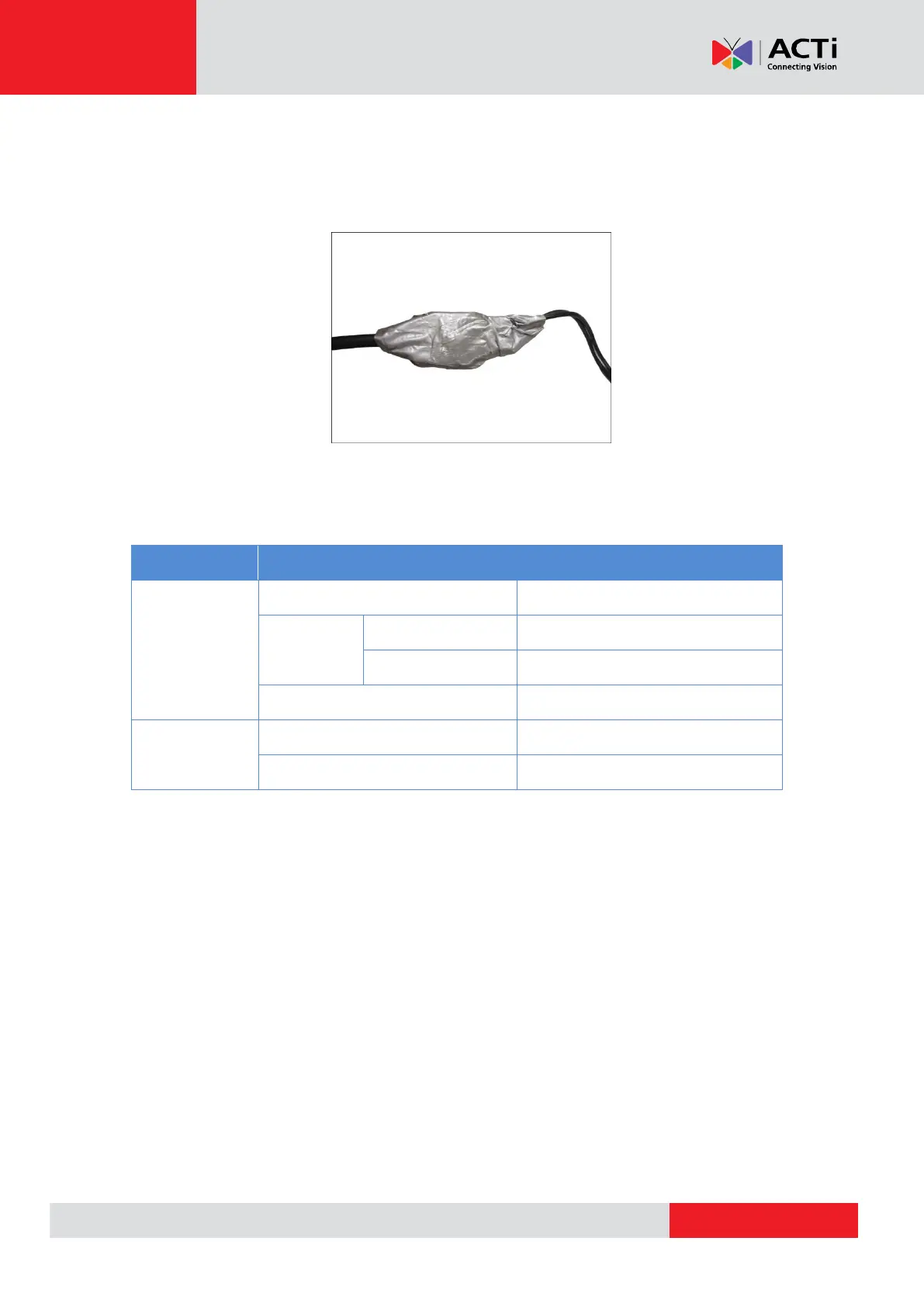
After mapping the wires to the terminal block, connect the terminal block to the DI/DO connectors
of the camera and be sure to protect the cable connection inside a junction box or wrap the
connection using a waterproof tape (can be purchased in hardware stores) if cable connection
will be exposed after installation. Sample below:
Typical Connection
The table below shows the DI/DO connection specifications:
TTL - compatible logic levels
Logic level 1: 3.1V ~ 30V
Transistor (Open Collector)
Based on these specifications, if the DI device has a voltage of 0V ~ 30V or the DO device has a
voltage of < 24V (< 50mA), then the camera can supply internal power to these devices and there
is no need to connect the DI/DO device to an external power source.