Hardware Manual
12
Connecting DI/DO Devices (Optional)
Depending on your needs, you may connect digital input/output devices, such as alarm to the
camera.
Check the device documentation for the pin mapping specifications. Map the pins of the device
to the supplied terminal block pins accordingly. Then connect the terminal block to the camera.
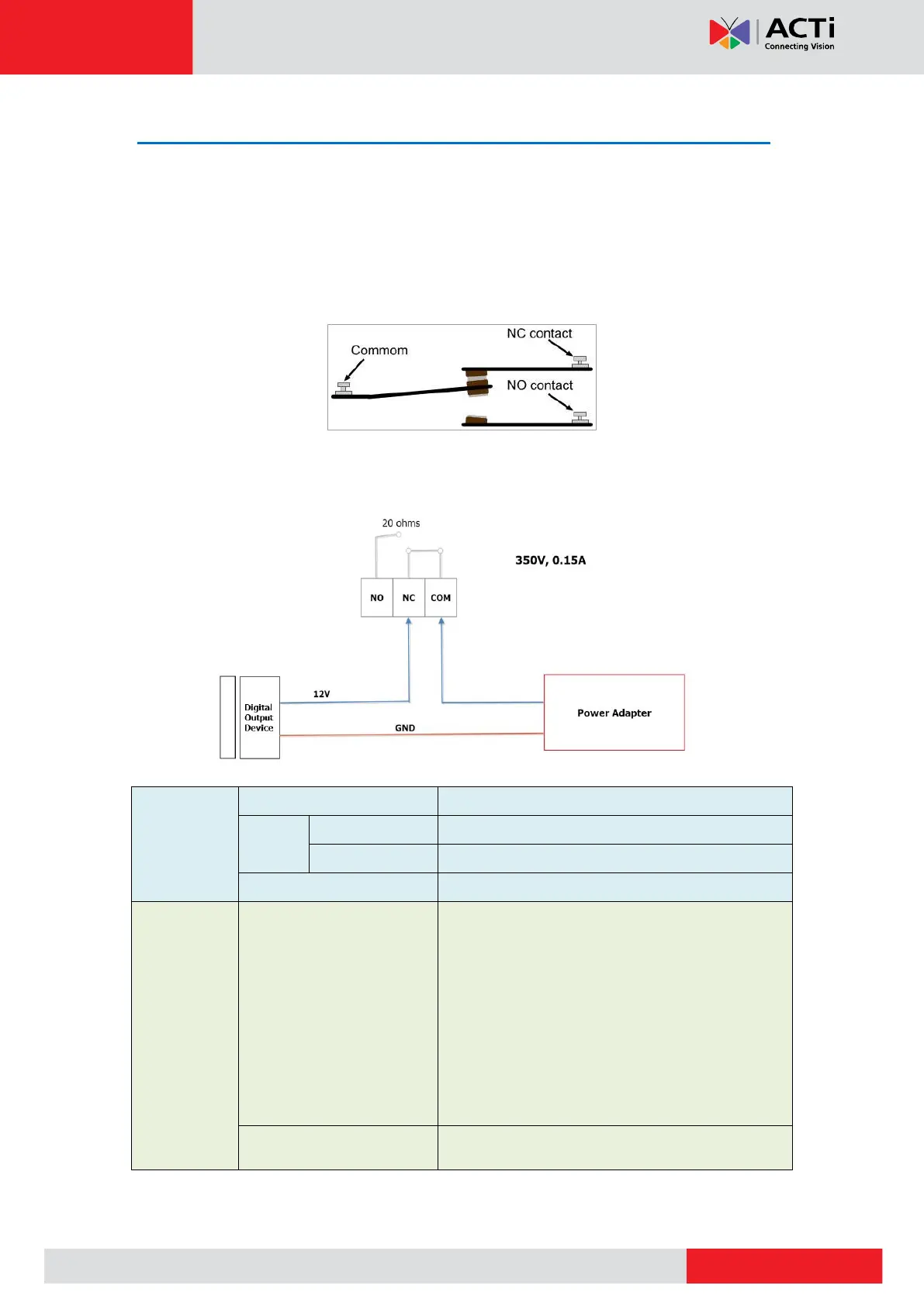
Below is a diagram on how the Digital Output of the camera work.
Some devices may not have Normal Close and Normal Open switches, thus only have DC12V
and GND wire connectors. In this case, map the wires according to the diagram below.
TTL-compatible logic levels
Logic level 1: 3.1V ~ 30V
Form C Solid-State Relay
Isolation test voltage 3750 VRMS
Typical RON 20
DC or peak AC load voltage 350 V
Continuous DC load current (form C
operation) 15 mA
Output power dissipation (continuous)
600 mW