15A MAX
FUSED
COM
DC
15A
20M
200
K
20K
2K
200
8CYL
6CYL
TACH
X10
5CYL
4CYL
8CYL
OHMS
15
A
250V MAX
250V MAX
15A MAX
FUSED
COM
DC
15A
20M
200
K
20K
2K
200
8CYL
6CYL
TACH
X10
5CYL
4CYL
8CYL
OHMS
15
A
10
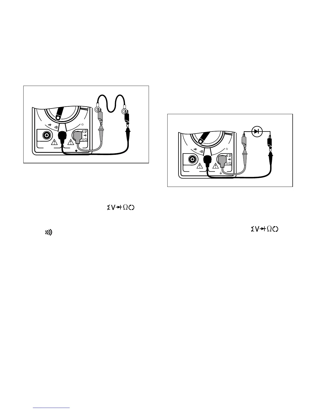
Testing for Continuity
Continuity is a quick way to do a resistance
test to determine if a circuit is open or closed.
The multimeter will beep when the circuit is
closed or shorted, so you don’t have to look at
the display. Continuity checks are usually
done when checking for blown fuses, switch
operation, and open or shorted wires.
Testing Diodes
A diode is an electrical component that allows
current to only flow in one direction. When a
positive voltage, generally greater than 0.7V,
is applied to the anode of a diode, the diode
will turn on and allow current to flow. If this
same voltage is applied to the cathode, the
diode would remain off and no current would
flow. Therefore, in order to test a diode, you
must check it in both directions (i.e. anode-to-
cathode, and cathode-to-anode). Diodes are
typically found in alternators on automobiles.
Performing Diode Test (see Fig. 11):
1. Insert BLACK test lead into COM test
lead jack.
2. Insert RED test lead into
test
lead jack.
3. Turn multimeter rotary switch to 2K
diode function. No beeper on diode test.
4. Touch RED and BLACK test leads to-
gether to test continuity.
Check display – should reset to 0.00.
5. Disconnect one end of diode from cir-
cuit.
Diode must be totally isolated from circuit
in order to test its functionality.
6. Connect RED and BLACK test leads
across diode and view display.
Display will show one of three things:
• A typical voltage drop of around 0.7V.
• A voltage drop of 0 volts.
• A “1” will appear indicating the multim-
eter is overranged.
Fig. 11
Fig. 10
To measure Continuity (see Fig. 10):
1. Insert BLACK test lead into COM test
lead jack.
2. Insert RED test lead into
test
lead jack.
3. Turn multimeter rotary switch to
200
function.
4. Touch RED and BLACK test leads to-
gether to test continuity.
Listen for tone to verify proper operation.
5. Connect RED and BLACK test leads
across component where you want to
check for continuity.
Listen for tone:
• If you hear tone – Circuit is closed or
shorted.
• If you don’t hear tone – Circuit is open.
Black
Red
Anode
Cathode
BlackRed