250V MAX
15A MAX
FUSED
COM
DC
15A
20M
200
K
20K
2K
200
8CYL
6CYL
TACH
X10
5CYL
4CYL
8CYL
OHMS
15
A
31
Position Type Sensors
Position sensors are potentiometers or a type of
variable resistor. They are used by the computer to
determine position and direction of movement of a
mechanical device. Typical position sensor applica-
tions are throttle position sensors, EGR valve posi-
tion sensors, and vane air flow sensors.
• If multimeter overranges on largest
range, then sensor is an open circuit
and is defective.
7. Move RED test lead to sensor SIG-
NAL pin.
• Refer to vehicle service manual for
location of sensor SIGNAL pin.
8. Operate Sensor.
Throttle Position Sensor:
• Slowly move throttle linkage from
closed to wide open position.
• Depending on hook-up, the display
reading will either
increase or de-
crease in resistance.
• The display reading should either
start
at or end at the approximate resis-
tance value measured in Step 6.
• Some throttle position sensors have
an Idle or Wide Open Throttle (WOT)
switch in addition to a potentiometer.
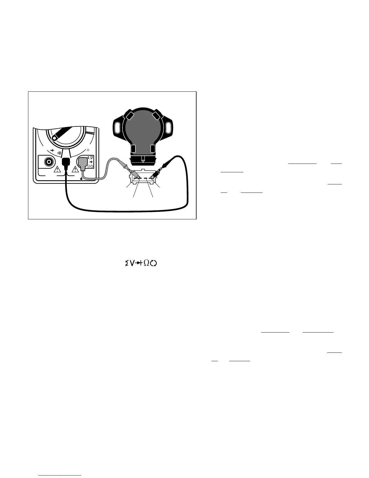
Fig. 32
Test Procedure (see Fig. 32):
1. Insert BLACK test lead into COM test
lead jack.
2. Insert RED test lead into
test
lead jack.
3. Disconnect wiring harness from sen-
sor.
4. Connect Test Leads.
• Connect RED test lead to sensor POWER
pin.
• Connect BLACK test lead to sensor
GROUND pin.
• Refer to vehicle service manual for loca-
tion of sensor POWER and GROUND
pins.
5. Turn multimeter rotary switch to 20K
Ω
range.
6. View and record reading on display.
• Display should read some resistance
value.
• If multimeter is overranging, adjust the
range accordingly. (See Setting the
Range on page 6.)
Typical Toyota Throttle
Position Sensor
Red
Black
POWER GROUND
SIGNAL IDLE SWITCH
• To test these switches, follow the Test-
ing Switches test procedure on page 13.
• When you are told to operate switch,
then move throttle linkage.
Vane Air Flow Sensor:
• Slowly open vane “door” from closed to
open by pushing on it with a pencil or
similar object. This will not harm sensor.
• Depending on hook-up, the display read-
ing will either
increase or decrease in
resistance.
• The display reading should either
start
at or end at the approximate resistance
value measured in Step 6.
• Some vane air flow sensors have an idle
switch and an intake air temperature
sensor in addition to a potentiometer.
• To test idle switch see Testing Switches
on page 13.
• When you are told to operate switch,
then open vane “door”.
• To test intake air temperature sensor see
Temperature Type Sensors on page 30.