29
• Connect BLACK test lead to remaining
heater pin.
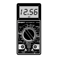
• Turn multimeter rotary switch to 200Ω
range.
• View reading on display.
• Compare reading to manufacturer's
specification in vehicle service manual.
• Remove both test leads from sensor.
6. Connect BLACK test lead to sensor
GROUND pin.
• If sensor is 1-wire or 3-wire, then
GROUND is sensor housing.
• If sensor is 2-wire or 4-wire, then
GROUND is in sensor wiring harness.
• Refer to vehicle service manual for Oxy-
gen Sensor wiring diagram.
7. Connect RED test lead to sensor SIG-
NAL pin.
8. Test Oxygen Sensor.
• Turn multimeter rotary switch to...
–2V range for Zirconia Type Sensors.
–200KΩ range for Titania Type Sensors.
• Light propane torch.
• Firmly grasp sensor with a pair of locking
pliers.
• Thoroughly heat sensor tip as hot as
possible, but not “glowing.” Sensor tip
must be at 660°F to operate.
• Completely surround sensor tip with
flame to deplete sensor of oxygen (Rich
Condition).
• Multimeter display should read...
–0.6V or greater for Zirconia Type Sen-
sors.
– an Ohmic(Resistance) value for Titania
Type Sensors. Reading will vary with
flame temperature.
• While still applying heat to sensor, move
flame such that oxygen can reach sensor
tip (Lean Condition).
• Multimeter display should read...
–0.4V or less for Zirconia Type Sensors.
– an overrange condition for Titania Type
Sensors. (See Setting the Range on page
6.)
9. Repeat Step 8 a few times to verify
results.
10.Extinguish Flame, let sensor cool, and
remove test leads.
11.Test Results.
Good Sensor:
• Heater Circuit resistance is within
manufacturer's specification.
• Oxygen Sensor output signal changed
when exposed to a rich and lean condi-
tion.
Bad Sensor:
• Heater Circuit resistance is not within
manufacturer's specification.
• Oxygen Sensor output signal did not
change when exposed to a rich and lean
condition.
• Oxygen sensor output voltage takes
longer than 3 seconds to switch from a
rich to a lean condition.