EN • 9
Chimney connector type: B23
The chimney must be connected to the boiler by means of a metal
pipe rising at an angle from the boiler to the chimney. It must be
easily removable in order to give access to the flue pipes when
servicing the boiler. A draught regulator must be installed on the
chimney in order to stabilise negative pressure.
The high efficiency of our boilers means that the flue
gases exit at low temperature. The attendant risk of
condensation may cause damage to some chimneys.
To avoid this risk we strongly advise that you line the
chimney.
Please contact your installer for further information
about chimney lining.
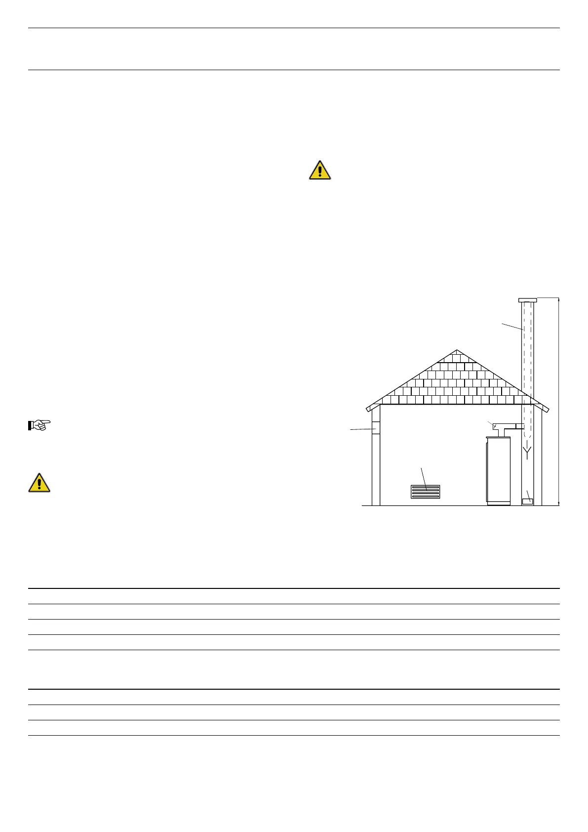
A. High level ventilation
B. Low level ventilation
C. Draught stabiliser
D. Flame inspection window
E. Height of lined chimney
F. Chimney diameter
INSTALLATION
BOILER ROOM
Important
• Never obstruct the ventilation.
• Do not store inflammable products in the boiler room.
• Avoid storing corrosive products such as paint, solvents, chlorine,
salt, soap or other cleaning products near the boiler.
Accessibility
The boiler room should be large enough to allow easy access to the
boiler. Minimum clearances around the boiler:
• To the front 500 mm
• To the rear 150 mm
• To the sides 100 mm
• Above 700 mm
Base
The base on which the boiler will be mounted must be made from
non-combustible materials.
Ventilation
The boiler room must have both low and high level ventilation.
By way of information, the table below gives the minimum
ventilation requirements according to Belgian regulations.
The user must ensure that his boiler room ventilation complies
with local regulations.
CHIMNEY CONNECTION
Important:
The boiler must be installed by a qualified engineer
in accordance with the local standards and codes of
practice.
The diameter of the chimney must not be less than the
diameter of the boiler’s chimney reducer.
Ventilation
25
F25
35
F35
45
F45
55
F55 G25 G35 G45 G55
Fresh air supply minimum m3/h 50 / 66 66 / 99 84 / 122 100 / 138 45 63 81 99
High level ventilation [A] dm2 2 2 2 2 1,5 1,5 1,5 1,5
Low level ventilation [B] dm2 1,5 1,5 1,5 1,5 / 2,1 1,5 1,5 1,5 1,7
Draught stabiliser [C] Ø 130 130 150 150 130 130 150 150
Chimney
25
F25
35
F35
45
F45
55
F55 G25 G35 G45 G55
E = 5 m Ø min. F mm 158 / 182 182 / 213 208 / 248 226 / 266 160 189 215 236
E = 10 m Ø min. F mm 133 / 153 153 / 179 175 / 209 190 / 223 135 159 181 199
E = 15 m Ø min. F mm 130 / 138 138 / 162 158 / 188 172 / 202 130 143 163 179
N.B.:
The figures for (B) and (C) only apply to type B23 connectors.
The above table is shown by way of indication only as regulations vary from country to country.