EN • 12
ELECTRICAL CONNECTIONS
ELECTRICAL BOILER CONNECTION
PRINCIPLE OF SUPPLY
The boiler operates on a single-phase supply of 230 V/50 Hz.
You should install a control box with main switch and 6 A fuses
externally to the boiler to allow the boiler to be isolated from the
supply for servicing and repairs.
STATUTORY COMPLIANCE
The installation must comply with your local standards and codes
of practice.
SAFETY
The stainless steel water tank must be provided with a separate
earth.
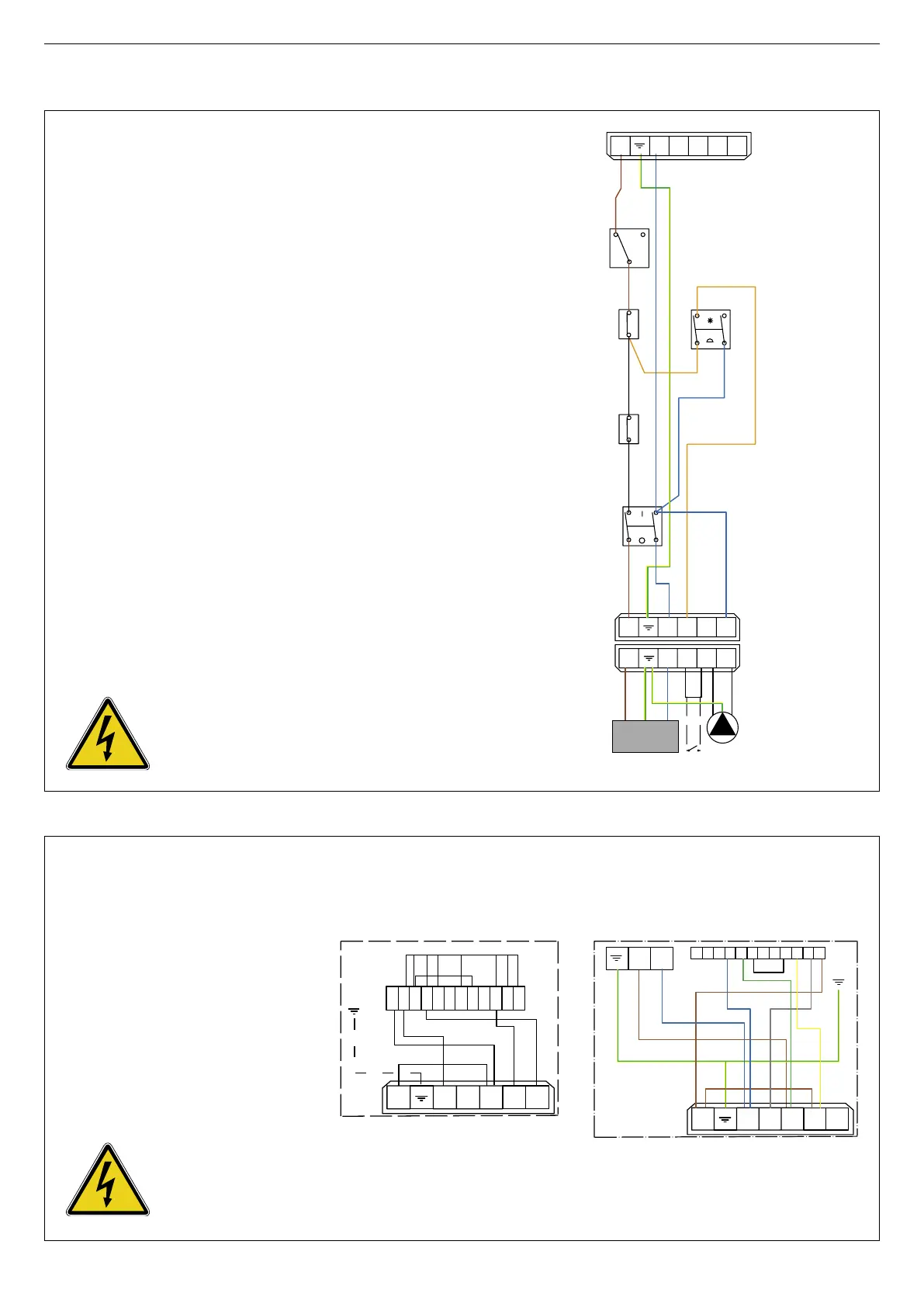
BOILER WIRING
1. Control thermostat [60/90°C]
2. Main switch
3. Summer / Winter switch
4. Manual reset high limit thermostat [103°C max.]
5. Power supply to boiler
6. Heating pump connection
7. Burner connection [7-pin plug]
8. Room thermostat [optional]
9. Thermal reset high limit thermostat [95°C]
B. Blue
Br. Brown
Bk. Black
Or. Orange
Y/Gr. Yellow / Green
The boiler must be isolated from
the electrical supply before any
work is carried out on it.
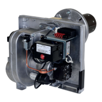
ELECTRICAL BURNERS CONNECTION
PH. Phase
N. Neutral
M. Motor
VM1. Magnetic valve 1
VM2. Magnetic valve 2
PF. Oil preheating
T. Ignition transformer
AL. Alarm
CF. Photoelectric cell
B. Blue
Br. Brown
Bk. Black
G. Grey
Gr. Green
Y. Yellow
Y/Gr. Yellow / Green
The boiler must be isolated from
the electrical supply before any
work is carried out on it.