Do you have a question about the ACV HeatMaster 25 TC and is the answer not in the manual?
Essential safety advice for appliance operation and installation.
Information on model availability and manufacturer's rights.
Immediate actions to take if gas is detected.
Precautions regarding flammable products, children, and supervision.
End-user setup limitations and references to installer's handbook.
Explanation of symbols used on packaging, appliance, and in manual.
Information on the appliance's rating plate for warranty claims.
Description of the ACVMax control panel, buttons, and display functions.
Explanation of key icons displayed on the ACVMAX interface.
Details on information displayed on the boiler's home screen.
Description of the stand-by and lockout screens and their meanings.
List and descriptions of all possible status messages displayed by the boiler.
Routine checks, common faults, and their solutions.
Instructions for initial boiler setup using the EZ function.
Guide for configuring heating settings without an outdoor sensor.
Guide for configuring heating settings with an outdoor sensor.
Guide for configuring domestic hot water (DHW) demand and settings.
Procedure to reset EZ settings and select display language/units.
Enabling/disabling circuits and viewing real-time boiler status.
Reviewing past lockout events and their details.
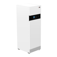
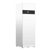
Introduction to the HeatMaster TC series and specific model details.
Diagram and list of components for the 25-35-45 TC models.
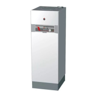
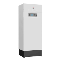
Diagram and list of components for the 70-85-120 TC models.
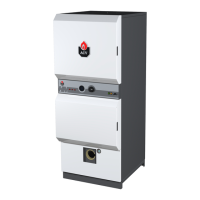
Illustration and labeling of the boiler's rear connections.
Table detailing physical dimensions for all HeatMaster models.
Required space around the boiler for safe installation and ventilation.
Table mapping gas types and country codes to boiler compatibility.
Detailed combustion characteristics, including gas flow and efficiency.
Data for flue pipe connections, including sizes and pressure drops.
Descriptions of various flue pipe connection types (e.g., C13, C33).
Methodology and examples for calculating flue pressure drop.
Guidelines for determining maximum flue pipe lengths in cascade systems.
Electrical specifications and wiring for the 25-35-45 TC models.
Illustration of internal cable routing for low and high voltage wiring.
Detailed electrical wiring diagram for the ACV Max control unit.
Electrical specifications and wiring for the 70-85 TC models.
Electrical specifications and wiring for the 120 TC model.
Specifications for domestic hot water performance at various temperatures.
Graphs illustrating pressure drop versus water flow rate.
Details on maximum service pressure and operating temperatures.
Recommendations for maintaining water quality to prevent system damage.
UK specific regulations for safety valve discharge pipe installation.
Worked example demonstrating how to size discharge pipes.
Table for sizing copper discharge pipes based on valve outlet.
Crucial safety guidelines for boiler installation procedures.
Key operational recommendations for a correct installation.
Safety advice on materials, ventilation, and corrosive products.
Essential guidelines for safe electrical connections during installation.
List of all items included in the boiler packaging.
List of necessary tools for the installation process.
Procedures for preparing the boiler prior to final placement.
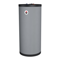
Diagrams and descriptions for hydraulic and DHW connections.
Illustrations for high and low temperature heating circuit connections.
Details on accessories for enhancing heating circuit control.
Procedure for removing and reinstalling the boiler's front and top panels.
Guidelines and steps for safely connecting the gas supply.
Instructions for converting the boiler from natural gas to propane.
Example configuration for high-temp heating with thermostat and outdoor sensor.
Schematic illustration of a typical heating system setup.
Procedure for setting up cascade systems using the EBV controller.
Critical safety precautions before initiating boiler start-up.
Required tools and essential checks before starting the boiler.
Step-by-step guide for filling the DHW and heating circuits.
Detailed steps for safely starting and operating the boiler.
Procedure for verifying and adjusting burner combustion parameters.
Safety guidelines, required tools, and shutdown procedures for maintenance.
Schedule and description of routine maintenance tasks for boilers.
Steps for safely draining the DHW tank and heating circuit.
Procedure for removal, check, and installation of the burner electrode.
Detailed instructions for removing and reinstalling the burner assembly.
Table specifying recommended torque values for component assembly.
Procedure for cleaning the internal heat exchanger.
Steps for safely restarting the boiler after maintenance completion.
Table of fault codes E01-E21 with descriptions and solutions.
Table of fault codes E25-E77 with descriptions and solutions.
Table of fault codes E79-E99 with descriptions and solutions.
| Category | Boiler |
|---|---|
| Maximum Input (Natural Gas) | 25 kW |
| Maximum Input (Propane) | 25 kW |
| Efficiency | 95% AFUE |
| Heat Exchanger Material | Stainless Steel |
| Mounting | Wall-mounted |
| Heating Capacity | 25 kW |
| Max Working Pressure | 3 bar |
| Ignition Type | Electronic Ignition |
| Flue Diameter | 80/125 mm |
| Fuel Type | Natural Gas, Propane |