Do you have a question about the ACV HR 321 and is the answer not in the manual?
Explains the concentric cylinder design of ACV tanks and how heating fluid warms domestic water.
Details the process of how the thermostat activates the pump to heat the water and when the pump stops.
Illustrates the stages of the ACV tank's operational cycle: discharged, recharging, charged, and draw-off.
Provides a description of the tank's components and materials.
Details the stainless steel internal tank, its welding, passivation, and corrugated design.
Describes the polyurethane foam or rock wool insulation used for heat retention.
Explains the steel casing, its preparation, and stove enamelling for durability.
Lists the components found on the control panel, including thermostat and thermometer.
Details how to adjust the thermostat control knob and its temperature settings.
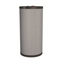
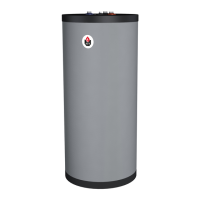
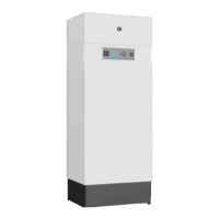
Describes ACV tanks as floor-standing units for sanitary hot water preparation.
Specifies stainless steel for the sanitary tank and mild steel for the heating tank.
Outlines the maximum temperature and pressure limits for primary and secondary circuits.
Details the GL models for low output boilers and domestic premises.
Describes HR models for low to average output boilers.
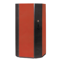
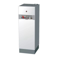
Highlights HR BE dual energy tanks for low to average output boilers with electric heating.
Covers JUMBO models for industrial premises with high sanitary water demand.
Provides diagrams and technical descriptions of the tank connections and types.
Presents data tables for GL, HR BE, HR, and JUMBO models including capacity and dimensions.
Specifies the maximum operating pressures for primary and secondary circuits for different models.
Details the test pressures for primary and secondary circuits for various tank models.
Presents performance data for sanitary water output at different temperatures and flow rates.
Lists performance figures for domestic hot water output and boiler efficiency.
Defines operating temperatures and correction coefficients for performance adjustments.
Explains how to calculate heat loss to the atmosphere using surface area and temperature difference.
Guides users on selecting the appropriate tank size based on installation needs.
Provides a formula to calculate tank size based on the number of rooms with baths and showers.
Offers a formula for sizing tanks based on apartment type, occupants, and heat consumption.
Presents a method to estimate tank requirements for sports centers based on shower usage.
Provides a chart to determine the correct tank model based on building standards 'N'.
Lists the values used for calculation: heating fluid temp, storage temp, and cold water temp.
Specifies the storage temperature of 85°C for chart calculations.
Advises on increasing expansion vessel size by 3% for installation water volume.
Details the primary heating circuit connections and boiler control.
Illustrates connecting a single tank with a primary pump and boiler control.
Shows the connection of a single tank with a three-way diverter valve.
Depicts parallel connection of multiple tanks with a primary pump.
Illustrates connecting sanitary water in series for maximum peak flow.
Shows connecting sanitary water in parallel for maximum continuous flow.
Shows single and multiple tank connections to a HEAT MASTER for peak flow.
Details series installation for low primary fluid return temperature, useful for heat recovery.
Warns that series installation may reduce sanitary hot water performance, requiring oversizing.
Presents principles for sanitary water connections with and without thermostatic mixing valves.
Diagram and description of the sanitary water circuit without a thermostatic mixing valve.
Diagram and description of the sanitary water circuit with a thermostatic mixing valve.
Explains how the sanitary expansion tank addresses water hammer and high pressure issues.
Describes how fast-closing valves cause water hammer, leading to noise and mechanical failure.
Explains how higher pressure leads to safety valve discharge and water loss.
Illustrates the sanitary water circuit connections and components.
Provides step-by-step instructions for draining the tank, including valve operations.
Advises on ensuring valve D is at the lowest point for complete tank draining.
Shows wiring diagrams for HR-GL-JUMBO and HR BE models.
Details the electrical connections for HR, GL, and JUMBO series tanks.
Presents the electrical wiring for the HR BE series, including thermostats.
Illustrates the installation of the 2.4 kW immersion heater for HR BE models.
Explains how the controller connects a water heater or dual energy unit to a boiler.
Describes 'Winter' mode for sanitary hot water priority, activating heating fluid and boiler burner.
Details 'Summer' mode where the boiler solely provides sanitary hot water.
Advises setting the boiler thermostat 10°C higher than the tank temperature.
Instructions for mounting the insulation and casing for JUMBO tanks.
Steps for attaching and sliding the half base plates into the tank base.
Procedure for joining the two half base plates using bolts.
Instructions for covering the tank's cylindrical part and top with rock wool.
Details on retaining the rock wool insulation using straps.
Fixing the four corner panels using studs for stability.
Temporarily fixing top panels to corners to hold them firm.
Sliding thermometer and thermostat bulbs into their respective pockets.
Attaching front, side, and rear panels and screwing them to the top panels.
Securing the side panel and tightening corner screws after alignment.
Steps for filling, pressurizing, purging, and operating the sanitary and heating circuits.
Recommendations for water pressure reduction and air purging during operation.
Details on routine maintenance, including checking safety valves and accessibility.
Instructions for safely replacing the immersion heater, including power disconnection.
Outlines the scope, period, limitations, and exclusions of the product warranty.
Provides detailed text for tender specifications for ACV tanks.
Lists specifications for HR, GL, and JUMBO tank models.
Details the specifications for the HR BE series of tanks.
Shows various certifications and approvals for ACV tanks from different regions.
Provides a comprehensive list of spare parts with corresponding codes for various tank models.
Lists spare parts specific to HR and HR BE tank series.
Details spare parts available for the GL series of ACV tanks.
Lists spare parts specifically for the JUMBO 800 model.
Details spare parts available for the JUMBO 1000 model.