This document provides comprehensive instructions for the installation, operation, and servicing of ECO, HL, and HLE series hot water tanks. It is intended for specifying engineers, installers, users, and service engineers.
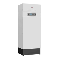
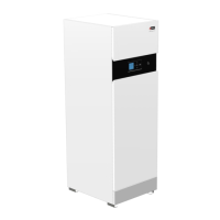
Function Description
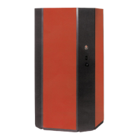
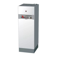
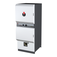
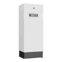
The ECO, HL, and HLE series hot water tanks utilize a "Tank-in-Tank" system, functioning as a heat exchanger with a built-in accumulator. This design consists of two concentric tanks: an inner tank for domestic hot water (secondary circuit) and an outer tank for the heating fluid (primary circuit). The heating fluid circulates between the two tanks, transferring heat to the domestic water.
The inner tank, the core of the system, is constructed from solid chrome-nickel stainless steel (304 or duplex grade), fully welded using the Tungsten Inert Gas (T.I.G.) technique. This material choice and manufacturing process, which includes pickling and passivation of convex bottoms and corrugation of the shell, enhance the tank's lifespan, corrosion resistance, and ability to withstand high pressures and temperature variations. The corrugated design also limits lime scale adherence by allowing the tank to expand and contract.
The outer tank, which contains the primary circuit water from the boiler, is made of carbon steel STW 22.
Thermal insulation is provided by soft polyurethane foam, 30 mm thick, ensuring minimal heat loss. The exterior casing is vinyl-coated, and the unit features a polypropylene cap.
The HLE models are additionally equipped with a 2200 W electric heating element, controlled by a dedicated thermostat, allowing them to function as electric domestic hot water heaters.
Operating Cycle: The thermostat initiates the pump, which loads the heating fluid. This fluid circulates around the inner tank, heating the domestic water. Once the desired temperature is reached, the thermostat stops the loading pump.
Important Technical Specifications
Operating Condition:
- Maximum service pressure (tank filled with water): 10 bar
- Heating circuit: 3 bar
- DHW circuit: 10 bar
Operating Temperature:
- Maximum temperature: 90°C
Water Quality:
- Chlorides: < 150 mg/L (304 Stainless steel)
- pH: 6 < pH < 8
Tank Characteristics (AT = 40°C, ambient T° of 20°C):
| Model |
Capacity (L) |
Primary fluid flow rate (m³/h) |
Primary pressure drop (mbar) |
Heating surface (m²) |
Losses in °C/h |
Peak flow at 40°C (L/10') |
Peak flow at 40°C (L/60') |
Peak flow at 40°C (L/h) |
Constant flow at 40°C (L/h) |
Pre-heating time (minutes) |
Coefficient (NL) |
Power (kW) |
Heating time, with 2.2 kW heating element, from 10 to 60°C (h) |
| ECO 100 |
100 |
2.2 |
17 |
1.26 |
0.28 |
236 |
784 |
1300 |
658 |
24 |
1.0 |
23 |
— |
| ECO 130 |
130 |
2.2 |
22 |
1.54 |
0.25 |
321 |
1049 |
1749 |
890 |
22 |
2.1 |
31 |
— |
| ECO 160 |
160 |
2.2 |
37 |
1.94 |
0.23 |
406 |
1349 |
2248 |
1132 |
22 |
3.0 |
39 |
— |
| HL 100 |
100 |
2.2 |
17 |
1.26 |
0.28 |
236 |
784 |
1300 |
658 |
24 |
1.0 |
23 |
— |
| HL 130 |
130 |
2.2 |
22 |
1.54 |
0.25 |
321 |
1049 |
1749 |
890 |
22 |
2.1 |
31 |
— |
| HL 160 |
160 |
2.2 |
37 |
1.94 |
0.23 |
406 |
1349 |
2248 |
1132 |
22 |
3.0 |
39 |
— |
| HL 210 |
210 |
3.7 |
45 |
2.29 |
0.21 |
547 |
1720 |
2867 |
1527 |
20 |
5.2 |
53 |
— |
| HL 240 |
240 |
4.2 |
51 |
2.94 |
0.21 |
700 |
2370 |
3950 |
1943 |
20 |
11.8 |
68 |
— |
| HLE 100 |
100 |
2.2 |
17 |
1.26 |
0.28 |
236 |
784 |
1300 |
658 |
24 |
1.0 |
23 |
2h 43' |
| HLE 130 |
130 |
2.2 |
22 |
1.54 |
0.25 |
321 |
1049 |
1749 |
890 |
22 |
2.1 |
31 |
3h 27' |
| HLE 160 |
160 |
2.2 |
37 |
1.94 |
0.23 |
406 |
1349 |
2248 |
1132 |
22 |
3.0 |
39 |
4h 20' |
| HLE 210 |
210 |
3.7 |
45 |
2.29 |
0.21 |
547 |
1720 |
2867 |
1527 |
20 |
5.2 |
53 |
5h 37' |
| HLE 240 |
240 |
4.2 |
51 |
2.94 |
0.21 |
700 |
2370 |
3950 |
1943 |
20 |
11.8 |
68 |
6h 37' |
Domestic Hot Water Expansion Vessel Capacity:
- 5 Litres: for 100 L models
- 8 Litres: for 130/160 L models
- 12 Litres: for 210/240 L models
Usage Features
Installation:
- Location: The tank should not be exposed to outside weather conditions. Choose a location that minimizes heat losses and pressure drops, ideally close to the boiler and the domestic hot water distribution system.
- Mounting: Can be installed on the floor or wall-mounted using supplied fixtures, depending on the model.
- HLE Models: Must be assembled with the heating element at the bottom (DHW pipes to the bottom).
- Horizontal Configuration: In horizontal installations, peak output and first-hour continuous output will be reduced. Oversizing the tank is recommended in such cases.
- Domestic Safety Unit: A domestic safety unit is mandatory and must not be placed directly above the tank to prevent water from dripping onto it. This unit must include an isolating valve, a non-return valve, a safety valve (set to < 10 bar), and a sanitary expansion vessel of appropriate dimensions.
- Pressure Reducer: If operating pressure exceeds 6 bar, a pressure reducer must be installed before the safety unit.
- Dielectric Union Fittings: Recommended to protect connections against corrosion when dissimilar metals (e.g., copper and galvanised steel) are present.
- Earth Connection: The sanitary tank must be directly connected to earth to avoid corrosion risks.
Commissioning:
- Filling the Tank: Both the domestic hot water tank (secondary) and the central heating tank (primary) must be filled and pressurised before use.
- DHW Tank: Close the drain cock, open the isolating valve, and bleed air by turning on a nearby hot water tap until flow stabilizes.
- Central Heating Tank: Close the drain cock, open isolation valves, and bleed air via the air vent on the upper part of the tank. Follow boiler instructions for filling.
- Pre-Start-up Checks: Verify correct installation of safety valves, proper discharge connections, filled tanks, air bleed, sealed air valve, correct pipe connections (hot/cold water, heating feed/return), correct electrical cabling, and thermostat setting.
- Thermostat Setting: Factory preset to 60-90°C. Turn clockwise to increase temperature, anticlockwise to reduce. Ensure boiler temperature is at least 10°C higher than the tank's thermostat.
- Legionella Risk: Maintain a minimum temperature of 60°C in storage and the hot water distribution network to prevent Legionella growth.
- Scalding Risk: ACV recommends using a thermostatic mixing valve set to provide water at 60°C or less to prevent scalding, especially for children, the elderly, and the disabled.
- Stratification Effect: When drawing small amounts of hot water repeatedly, stratification can occur, leading to very high temperatures in the upper layer. A thermostatic mixing valve will prevent excessively hot water from reaching outlets.
Maintenance Features
Periodic Checks by the User:
- Boiler Pressure: Check boiler pressure gauge regularly; it should be between 0.5 and 1.5 bar.
- Visual Inspection: Carry out a monthly visual inspection of valves, connections, and accessories for leaks or malfunctions.
- Safety Valve: Periodically check the air valve located on the upper part of the tank. Manually operate the safety valve once a year to discharge hot water. This prevents calcification and ensures proper operation.
Annual Service:
- An approved installer or maintenance company must perform an annual service.
- Air Bleed: Check and bleed air from the system.
- Boiler Pressure: Check the pressure on the boiler's pressure gauge.
- Safety Valve: Manually operate the boiler's hot water safety valve once a year.
- Circulator's Maintenance: Follow the circulator's maintenance instructions.
- Electrical Components: Ensure all electrical accessories are working properly (refer to manufacturer's instructions).
- Discharge Pipe: The discharge pipe should be open to the atmosphere.
- Expansion Problem: If the discharge pipe drips continuously, it may indicate an expansion problem or collapsing of the valve.
Replacement of the Electric Heating Element of the HLE:
- Switch off and disconnect the main power supply to the appliance.
- Drain the primary tank.
Emptying:
- Risk of Frost Exposure: Empty the tank if it is to be switched off for extended periods in conditions where frost exposure is a risk.
- Antifreeze: If antifreeze is needed in the primary circuit, it must be compatible with public hygiene rules and non-toxic (food-type Propylene Glycol is recommended). Consult the manufacturer for compatibility with tank materials.
- Draining Procedure (Primary Circuit): Before draining the domestic hot water, insulate the tank to bring the central heating pressure (primary circuit) down to 1 bar to protect the tank against a risk of collapsing.
- Antifreeze Compatibility: If the central heating circuit does not contain any antifreeze, both the central heating and hot water circuits should be drained.
- Never use car antifreeze or undiluted antifreeze. This can cause serious injury, death, or damage to the premises.