EN • 4
661Y0400.F
ENGLISHFRANCAISNEDERLANDSESPAÑOLITALIANO
РУССКИЙ
DEUTSCH
DESCRIPTION OF THE SPECIFICATIONS
“Tank-in-Tank” system
“Tank-in-Tank” is a heat exchanger with a built-in accumulator, made
up of two concentric tanks: the inner tank contains domestic water
to be reheated (secondary) and the outer tank contains the heating
fluid (primary) which circulates between the two tanks and transfers
its heat to the domestic water.
Hot water exchanger accumulator
The inner tank is the heart of the tank: it is subject to the
aggressiveness of the supply water, to high pressures and to
variations in temperature. This tank is made of solid chrome-
nickel stainless steel (stainless steel 304 or duplex), fully welded
under argon protection using the Tungsten Inert Gas (T.I.G.)
technique.
Before assembly, the convex bottoms are pickled and passivated in
order to improve the tank’s lifespan and in particular its resistance to
corrosion. The shell is corrugated all the way up using an exclusive
manufacturing process. This design gives considerable resistance to
pressure and limits the adherence of lime scale by allowing the tank
to expand and contract.
Outer tank
The outer tank containing water from the primary circuit arriving
from the boiler, is made of carbon steel STW 22.
Thermal Insulation
Soft polyurethane foam - 30 mm thickness.
Lining
Exterior of casing vinyl coated and polypropylene cap.
Electric heating element in HLE
The HLE tank is equipped with one 2200 W heating element
controlled by the thermostat of the HLE.
Description
1. Air valve
2. Steel STW 22 outer tank
3. Domestic hot water outlet
4. Pocket containing the control thermostat
5. Electric heating element 2200 W [HLE only]
6. Insulating foam
7. Polypropylene cap
8. Polyurethane foam insulation
9. Stainless steel (304 or Duplex) inner tank
10. Domestic water return
11. Outlet and return pipes for the heating fluid
12. Domestic cold water inlet
INTRODUCTION
DESCRIPTION OF OPERATION
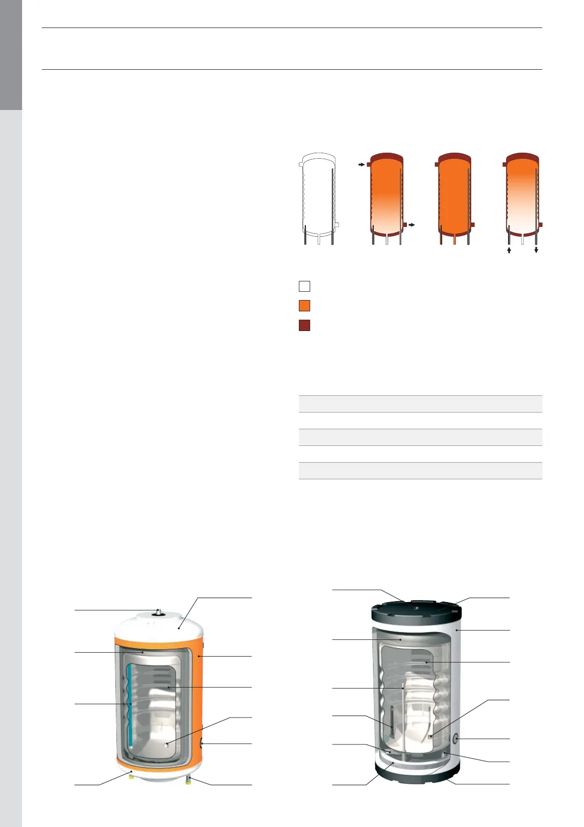
Operating cycle
The thermostat is triggered and starts up the pump which loads the
heating fluid. This fluid circulates around the inside tank and heats
up the domestic water. When the required temperature is reached,
the thermostat stops the loading pump.
Losses when shut down in °C/h
Models Losses in °c/h
ECO 100 / HL 100 / HLE 100 ΔT = 40°C 0,28
ECO 130 / HL 130 / HLE 130 ΔT = 40°C 0,25
ECO 160 / HL 160 / HLE 160 ΔT = 40°C 0,23
HL 210 / HLE 210 ΔT = 40°C 0,21
HL 240 / HLE 240 ΔT = 40°C 0,21
Temperature losses with ambient T° of 20°C
OFF Reheating Running Tepping
Cold Water
Heating fluid
Domestic hot water
4
3
10
1
9
11
8
2
12
6
5
7
7
12
10
1
9
11
8
2
3
7
7