Starting from the left, here are what each pinout connects to:
RIN - this is a duplicate of the audio input terminal block, right channel
LIN - this is a duplicate of the audio input terminal block, left channel
AGND - analog reference ground, the 'quieter' ground for audio signal referencing
SDA - i2c digital signal data, if using Digital Mode to control volume over i2c
SCL - i2c digital signal clock, if using Digital Mode to control volume over i2c
Vi2c - the i2c voltage reference for logic. Only used in Digital mode - connect to 3V or 5V whichever your
microcontroller uses
SHDN - digital Shutdown pin. Connect to ground to turn off the entire chip and put it into low power mode
MUTE - digital Mute pin. Connect to ground to turn off only the audio output stages, its faster than shutdown and
keeps the digital i2c audio levels
SYNCO - Sync output, this is the high frequency signal from the PWM generator, about 1.4MHz
SYNC - Sync input, for advanced users who want to clock in their own PWM frequency, keep it above 800KHz.
AD1 - I2C address select pin #1
AD2 - I2C address select pin #2
GND - Power ground
VDD - 5-12VDC power, from the terminal block/DC jack
after
the polarity protection. You can use this to power
your other projects that can handle 5-12VDC power input.
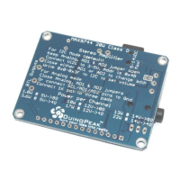
The solder jumper on the back allows you to connect AGND (analog ground) to DGND (digital ground)