8 9
Visual Alert
The TPX™ Visual Alert is designed to be mounted on any part of the
motorcycle that can easily be seen by the rider.
There are two mounting options for the Visual Alert.
Option 1: Using Double-Sided Adhesive Tape
Determine an appropriate location for mounting the Visual Alert. The
best location is one that encompasses the rider’s peripheral field of
view, with the LEDs pointed directly at the rider’s face. The surface
directly above the gauges is an ideal location on most motorcycles.
Clean the bottom surface of the Visual Alert and the chosen mounting
surface on the motorcycle with mild soap and water or alcohol. Rinse
with water to remove all traces of soap if necessary.
Once the surfaces are clean and dry, remove one liner of the Double-
Sided Adhesive Tape and apply to the bottom surface of the Visual Alert.
Figure 2
USING THE
TPX™ SYSTEM PRO
INSTALLATION
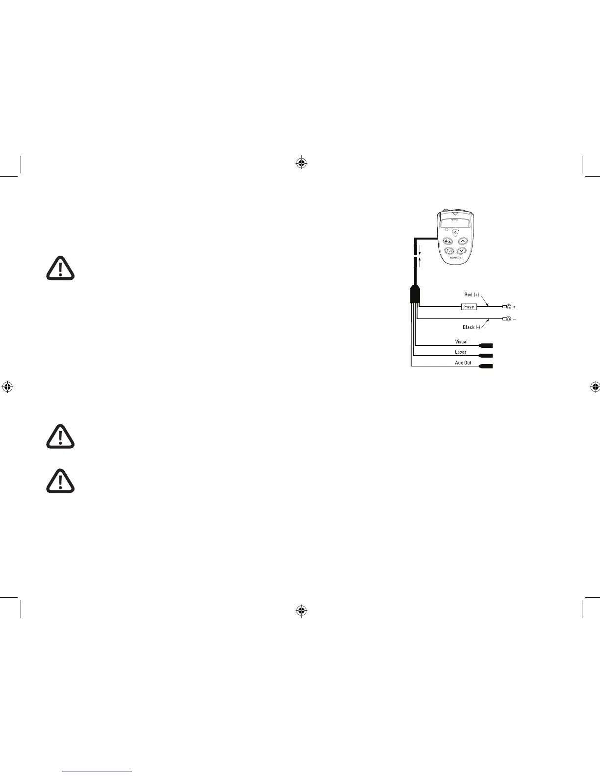
Wiring the System
Warning: Installation of the TPX™ System PRO should be
performed by a qualied technician. Improper installation may
interfere with the safety and proper operation of the product
and/or vehicle.
Power
The TPX™ Detector Unit is powered by the motorcycle’s 12V power source.
If the motorcycle’s power output is not 12V, a voltage adapter is required.
To provide power to the unit, connect the red (+) terminal cable to a switched
power wire on the motorcycle and the black (-) terminal cable to a ground
point. Alternatively, you can also connect the red (+) terminal cable to the
positive (+) terminal of the battery and the black (-) terminal cable to the
negative (-) terminal of the battery. Route the Wiring Harness through the
motorcycle and plug the Wiring Harness Plug into the Wiring Harness Jack on
the Detector Unit as shown in Figure 2.
Warning: Connecting the Wiring Harness directly to the battery
with the Detector Unit connected may drain the battery if the
motorcycle is not operated for an extended period, even with
the Detector Unit turned off. Disconnect the Wiring Harness
Plug if the Detector Unit is not going to be used for an extended
period of time.
Warning: Do not connect Wiring Harness Plug into the Detector
Unit before positive (red) and negative (black) terminal cables
are connected to the bike’s battery.
NOTE: The system is supplied with caps for the Wiring Harness Plug and
the Detector Unit Power Input. When not in use, place the caps over the
connectors to help prevent corrosion.
NOTE: The Wiring Harness is designed with a “c-clip” on the plug. This clip
can be used to secure the plug to the Quick Release Plate post for cable
management purposes.
Wiring Harness Plug
•
•
•